


Operation
User Diagnostics
56 Operating Manual for XPR Series Power Supply
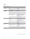
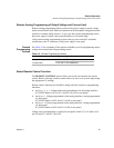
Table 3.3 User Diagnostics
Symptom Check Further Checks and Corrections
No output and the
display is blank.
Is input voltage within specified
range?
Connect to appropriate voltage source.
See page 32.
Power switch ON? Turn on power.
Internal circuit? See your service technician.
No output but the
display turns on.
OVP LED turned on? See page 51.
Front panel INT LED turned on? See page 53.
OTP LED turned on? See page 54.
Current limit set to zero? See page 49.
Voltage control set to zero? See page 49.
LCL/RMT LED turned on? If using remote analog control, check
your analog programming source
(Section 4).
Is front panel AC LED turned on? Connect unit to AC supply in specified
range. See page 33.
Internal circuit. See your service technician.
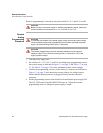
Output not adjustable. Is unit in current limit mode? (CC
LED turned on.)
Turn current knob clockwise to increase
current limit. Reduce load if current is at
maximum. See page 49.
Is unit in remote mode? (RMT LED
turned on.)
If using remote analog control, check
your analog programming source
(Section 4).
Is unit at maximum voltage or current
limit?
Reduce load for lower voltage or current
requirement.
Output voltage
fluctuating or regulation
poor.
Is unit at current limit? Increase current limit setting or reduce
load. See page 49.
Is input voltage within specified
range?
Connect to appropriate AC voltage
source.
See page 33.
Is unit under remote analog control? Ensure program source is stable.
Internal circuit. See your service technician.
Output oscillating. Internal circuit. See your service technician.