


Remote Operation
Remote Monitoring of Output Voltage and Current
64 Operating Manual for XPR Series Power Supply
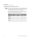
Remote Monitoring of Output Voltage and Current
Readback
Signals
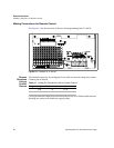
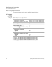
The J1 connector on the rear panel provides access to calibrated readback signals for
remote monitoring of the output voltage and current. Rear panel switches S1-3 and
S1-4 allow you to select either a 0-5 Vdc or a 0-10 Vdc range for the output. The
readback signal represents 0 to 100% of the power supply's output.
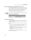
See Table 4.4 for the required J1 connections and switch settings for remote
monitoring of readback signals with 0-5 Vdc or 0-10 Vdc outputs. Use shielded pair
wiring (20 to 24 AWG) and ground the shield to the chassis.
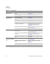
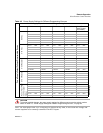
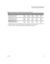
Table 4.4 Power Supply Settings for Remote Monitoring of Readback Signals
Readback Signal
J1 Connection
Signal (+)
J1 Connection
Return (–)
Switch S1 Setting
Output Voltage
(0-5 Vdc)
J1-4 J1-6 S1-3= OFF
Output Voltage
(0-10 Vdc)
J1-4 J1-6 S1-3=ON
Output Current
(0-5 Vdc)
J1-5 J1-6 S1-4= OFF
Output Current
(0-10 Vdc)
J1-5 J1-6 S1-4=ON