


Operation
Using the Shutdown Function (Output ON/OFF)
Release 1.1 53
Using the Shutdown Function (Output ON/OFF)
Use the shutdown function to disable or enable the supply’s output so that you can
make adjustments to either the load or the power supply without shutting off the
power supply. Activate this function from the front panel at any time by using the
OUT ON/OFF switch. You can also activate it via remote control through the rear
panel J1 Programming and Monitoring connector, using a 4 V to 15 V signal or a
transistor-transistor logic (TTL) compatible signal. The input lines for the Interlock
circuit are optically isolated.
Controlling
Output
ON/OFF via
Front Panel
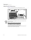
The OUT ON/OFF switch is a press ON/press OFF switch located on the power
supply’s front panel. Push the switch to its IN position to disable the output. The
output voltage and current fall to zero and the OFF LED turns on. Push the switch
once more to reset it to its OUT position and resume normal power supply operation.
(ON LED turns on.)
Controlling
the Interlock
Function via
the J1
Connector
The Interlock (TTL Shutdown) circuit accepts a 4 V to 15 V signal to disable or
enable the power supply output. Make connections for signals at connector J1,
located on the unit’s rear panel. Set rear panel switch S1-7 to select signal logic. (See
Table 3.1, on page 53.)
To activate the Interlock (TTL Shutdown) function:
1. Turn OFF the power supply.
2. Connect the signal source to J1 connector terminal 12 (Interlock Input/positive)
and terminal 11 (Interlock Return).
3. Set switch S1-7 to select the desired circuit logic as set out in Table 3.1.
4. Turn on the power supply. The power supply will operate as described in the
Supply Output column in Table 3.1, according to the logic that you select and the
level of the input signal. The INT (Interlock) LED on the front panel turns on
when the Interlock circuit is activated.
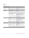
Table 3.1 Switch Settings for Interlock Circuit Logic
Switch S1-7 Setting Source Signal Signal Level Supply Output INT LED
OFF
(Active low, default)
4-15 V HIGH OFF ON
0-0.4 V LOW ON OFF
ON
(Active high)
4-15 V HIGH ON OFF
0-0.4 V LOW OFF ON