


Installation
Load Connections
Release 1.1 41
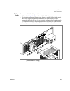
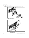
Load Connections
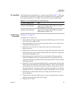
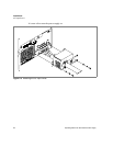
Make load connections at the rear of the power supply at the positive and negative
output bus bars or to the 4-terminal wire clamp connector, depending on the model.
(See Figure 2.6.)
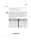
Wire Size The wire should be one size larger than necessary to accommodate the required
output current. Normally, the next largest commonly used gauge is used. For
example, use 10AWG for 20A, and 8AWG for 30A.
Isolation The wire must have a suitable insulating coating that will prevent arcing between the
positive and negative output lines, and must be rated for 105
°C operation.
WARNING
Exercise caution when operating the power supply. High energy levels can be stored
at the output terminals on a power supply in normal operation. In addition, potentially
lethal voltages exist in the power circuit and on the output and sense connectors of a
power supply with a rated output greater than 40V. Filter capacitors store potentially
dangerous energy for some time after power is removed.
!
CAUTION
When making connections to the bus bars, ensure that each terminal’s mounting
hardware and wiring assembly are placed to avoid touching the other terminal and
shorting the power supply outlet. Heavy connecting cables must have some form of
strain relief so they don’t loosen the connections or bend the bus bars.