


Installation
Basic Tests
Release 1.1 37
Voltage Mode
Operation
Check
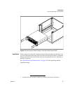
1. Ensure the voltage and current controls on the front panel are turned fully
counter-clockwise.
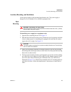
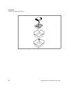
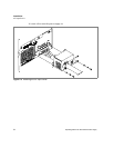
2. Connect a DVM to the output terminals on the rear panel, observing correct
polarity.
3. Turn the current control a 1/2-turn clockwise. Slowly turn the voltage control
clockwise and observe both the front panel voltmeter and the DVM.
4. Compare the DVM reading with the front panel voltmeter reading to verify the
accuracy of the internal voltmeter. Both readings should be within the error
specification for the display. The minimum control range is from zero to the
maximum rated output for the power supply model. The voltage mode CV LED
turns on.
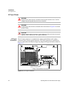
5. Press OUT ON/OFF button to turn the DC output OFF.
6. Turn the front panel AC power switch to OFF.
Current Mode
Operation
Check
1. Ensure that the front panel power switch is set to OFF.
2. Turn the voltage and current controls on the front panel fully counter-clockwise.
3. Connect the DC shunt across the output terminals on the rear panel.
4. Connect the DVM across the DC shunt.
5. Turn the AC power switch to ON.
6. Turn the voltage control one (1) or two (2) turns clockwise.
7. Turn the current control slowly clockwise.
8. Compare the DVM reading with the front panel ammeter reading using I=V/R
where I is the current, V is the DVM reading, and R is the DC shunt resistance.
The minimum control range is from zero to the maximum rated output for the
power supply model. The current mode CC LED turns on.
9. Press OUT ON/OFF button to turn the DC output OFF.
10. Turn the front panel power switch to OFF.
11. Disconnect the DVM and the shunt.