


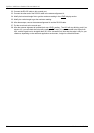

ExpWave 240B Secure Outdoor Ethernet Radio Link
Hardware Installation 2-7
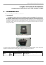
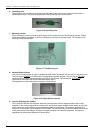
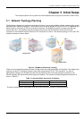
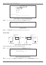
1. The whole installation procedure begins from the indoor to the outdoor installation.
2. Choose an appropriate place for the network/power injector. You might hang it on the wall or just place it
on the desk.
3. Connect the TO LAN
port of network/power injector and your CPE by the Cat-5 cable (2m in length).
4. Plug the switching power adapter into the 110V/220V outlet. Plug the output 48V into the network/power
injector POWER
port.
5. Connect the TO RADIO
port with Cat-5 cable (20m in length) and pull the special connector end of this
cable to the outdoor.
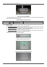
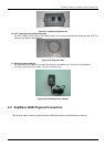
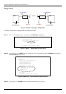
6. When the antenna alignment at both AP and AC sites are completed or the link is established, the LED
“ACK”
will stop blinking .
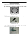
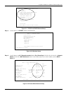
7. Assemble the mounting kit like the one shown in the following picture.
Figure 2-18 The mounting kit assembly
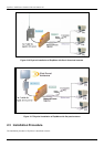
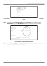
8. When the outdoor unit is accompanied with an omni-directional antenna, only one mounting is needed.
When the outdoor unit is accompanied with a flat panel antenna, two mounting kit is needed.
9. Choose an appropriate place for the outdoor unit. The chosen sites you plan to install the ExpWave 240B
should have a clear line-of-sight path.
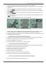
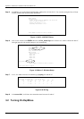
Install the outdoor unit with the omni-directional antenna
10. Assemble the mounting kit with the outdoor unit and the grounding wire should be connected together.
11. Connect the omni-directional antenna to the antenna port of the outdoor unit.
12. Place this assembled one on a stable rod.
13. Connect the other end of the grounding wire to the ground position.
Install the outdoor unit with the flat panel antenna
14. Assemble the mounting kit with the outdoor unit and the grounding wire should be connected together
15. Connect the RF cable to the antenna port of the outdoor unit.
16. Assemble the mounting kit with the flat panel antenna.
17. Place this flat panel antenna on a stable rod.
18. Place the outdoor unit on this stable rod also.
19. Connect the other end of the RF cable to the flat panel antenna.
20. Connect the other end of the grounding wire to the ground position.
Use the antenna alignment kit AK-100 to maximize the signal strength.
21. Open the cover of the console port of the access client unit.