AES-100 User’s Guide
2-2 Hardware Overview
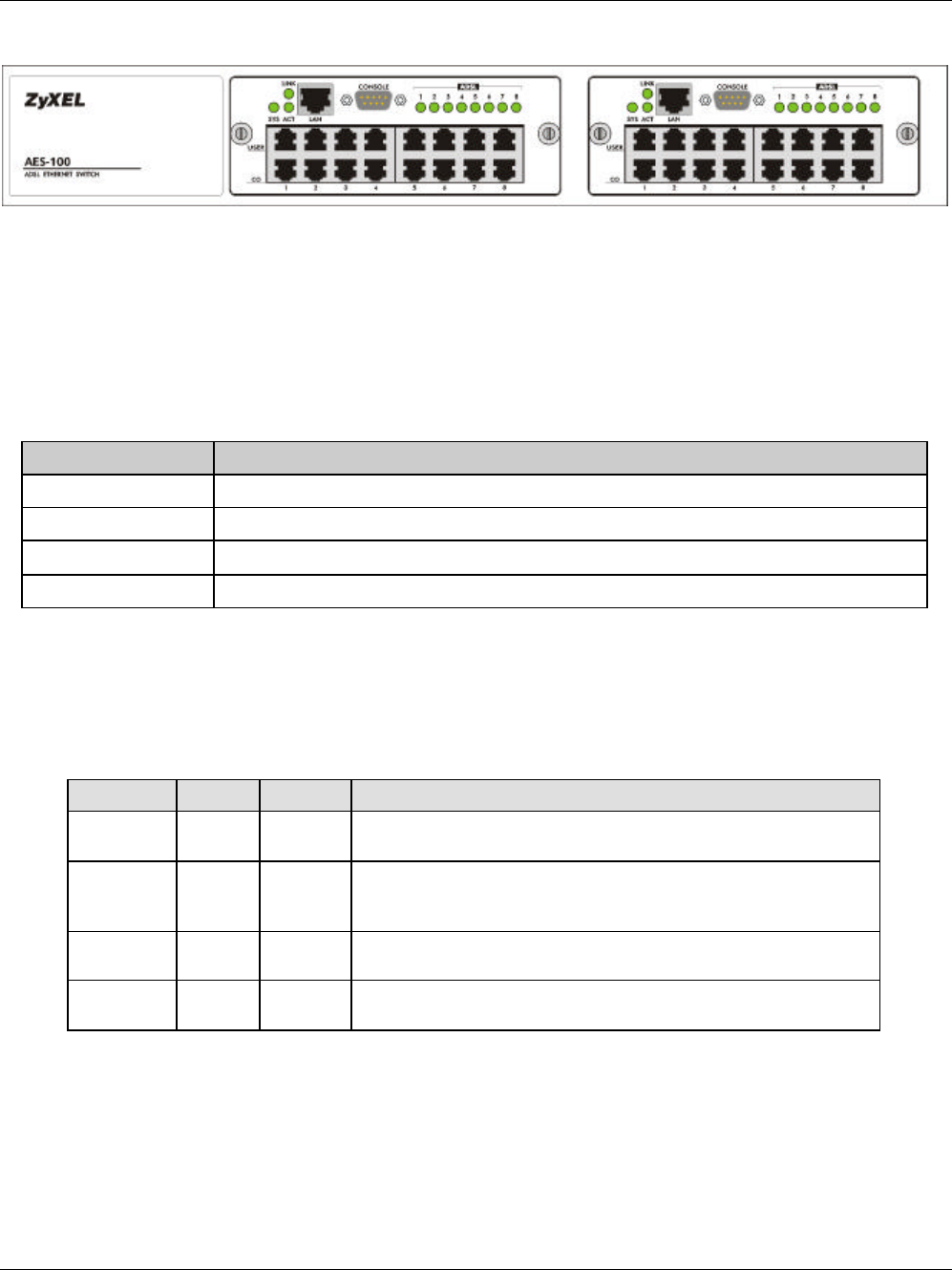
Figure 2-1 AES-100 Front Panel
2.3.1 Front Panel Ports
The following table describes the ports on the front panel of an AES-100 network module.
Table 2-1 Front Panel Ports of an ADSL Network Module
PORTS DESCRIPTION
LAN The LAN port is a 10 Mbps Ethernet port for connection to a router.
CONSOLE The CONSOLE port is an RS-232 port for configuring the AES-100.
USER 1-8 The USER port connects to the user (subscriber) ADSL equipment.
CO 1-8 The CO port connects to the central office or a PBX.
2.3.2 Front Panel LEDs
The following table describes the LED indicators on the front panel of an AES-100 network module.
Table 2-2 AES-100 Network Module LED Descriptions
LED COLOR STATUS MEANING
LINK Green On
Off
The LAN port link is up.
The LAN port link is down.
SYS Green On
Off
Blinking
Your AES-100 Network Module is on and functioning properly.
The system is not ready or has a malfunction.
The system is initializing.
ACT Green Off
Blinking
The LAN port is not active.
Data is being sent.
ADSL 1-8 Green
On
Off
The ADSL link is up.
The ADSL link is down.
2.4 Console Port
For the initial configuration, you need to use terminal emulator software on a computer and connect it to the AES-
100 through the console port. Connect the male 9-pin end of the console cable to the console port of the AES-100.
Connect the other end (either a female 25-pin or female 9-pin) to a serial port (COM1, COM2 or other COM port)


