


3.11 LINEAR INPUT SCALE RANGE MAXIMUM
This parameter, applicable only if a linear input is fitted, defines the scaled input value
when the process variable input is at its maximum value. It is adjustable between –1999
and 9999 (with decimal point as defined by Linear Input Decimal Point Position). The
default value is 1000. This parameter can be set to a value less than (but not equal to)
Linear Input Scale Range Minimum, in which case the sense of the input is reversed.
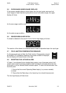
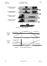
3.12 RECORDER OUTPUT SCALE MINIMUM
This parameter defines the value of the process variable at which the Recorder Output
reaches its minimum value; for example, for a 0 - 5V Recorder Output, this value
corresponds to 0V. It may be adjusted within the range –1999 to 9999. The decimal
point position for the Recorder Output is always the same as that for the process
variable input range. The default value is Input Range Minimum. This parameter is not
applicable if the Recorder Output option is not fitted.
NOTE: If this parameter is set to a value greater than that for the
Recorder Output Scale Maximum (see Subsection 3.13), the
relationship between the process variable value and the Recorder
Output is reversed.
3.13 RECORDER OUTPUT SCALE MAXIMUM
This parameter defines the value of process variable at which the Recorder Output
reaches its maximum value; for example, for a 0 - 5V Recorder Output, this value
corresponds to 5V. It may be adjusted within the range –1999 to 9999. The decimal
point position for the Recorder Output is always the same as that for the process
variable input range. The default value is Input Range Maximum. This parameter is not
applicable if the Recorder Output option is not fitted.
NOTE: If this parameter is set to a value less than that for the Recorder
Output Scale Minimum (see Subsection 3.12), the relationship
between the process variable/setpoint value and the Recorder Output
is reversed.
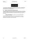
3.14 OPERATOR MODE DISPLAY STRATEGY
This defines the sequence of parameter displays available in Operator Mode (see
NOTES ON TABLE 3-1).
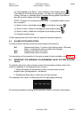
3.15 EXIT FROM SET UP MODE
To leave Set Up Mode, select the initial Operator Mode display (process variable value)
then depress the Raise and Scroll keys simultaneously, whereupon the SET indicator
will go OFF and the instrument will return to Operator Mode.
NOTE: An automatic return to Operator mode will be executed if there
is no key activity in Set Up Mode for one minute.
OM067-3 November, 2000 3-5
59039
1
8
-DIN Digi tal In di ca tor Sec tion 3
Prod uct Man ual - Vol ume I Set Up Mode