


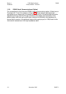
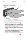
2.2 REMOVING/REPLACING THE OUTPUT 2/OUTPUT 3 OPTION PCBs
With the instrument removed from its housing:
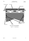
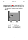
1. Gently push the rear ends of the CPU PCB and Power Supply PCB apart
slightly, until the two tongues on each of the Output 2/Output 3 Option PCBs
become dis-engaged - see Figure 2-2B; The Output 2 Option PCB tongues
engage in holes in the Power Supply PCB and the Output 3 Option PCB
tongues engage in holes on the CPU PCB.
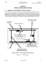
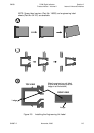
2 . Carefully pull the required Option PCB (Output 2 or Output 3) from its
connector (Output 2 Option PCB is connected to the CPU PCB and Output 3
Option PCB is connected to the Power Supply PCB) - see Figure 2-2C. Note
the orientation of the PCB in preparation for its replacement.
Adjustments may now be made to the link jumpers on the CPU PCB and (if DC output)
the Output 2 PCB. The replacement procedure is a simple reversal of the removal
procedure.
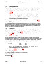
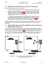
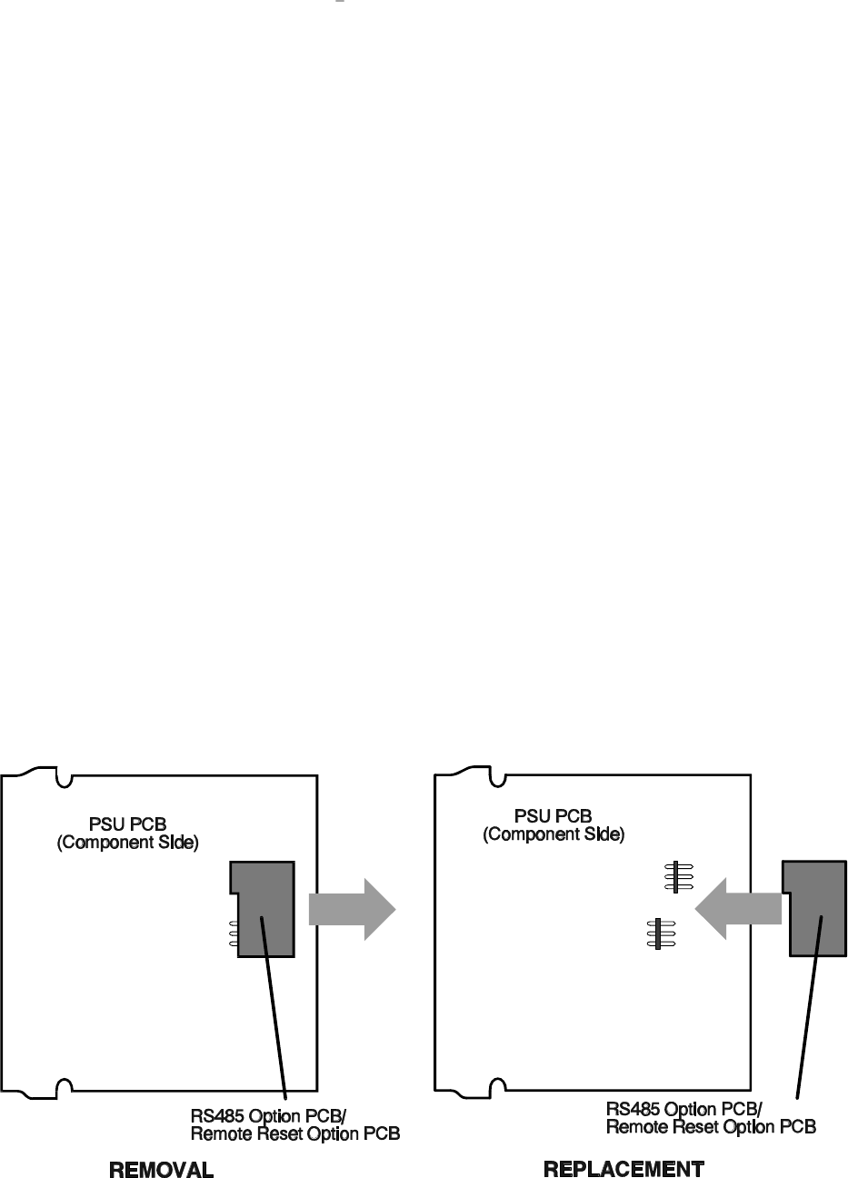
2.3 REMOVING/REPLACING THE RS485 COMMUNICATIONS OPTION PCB OR
REMOTE RESET OPTION PCB
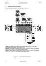
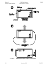
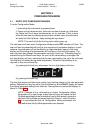
The RS485 Communications Option PCB or Remote Reset Option PCB is mounted on
the inner surface of the Power Supply PCB and can be removed when the instrument is
removed from its housing (see Subsection 2.1) by pulling the Option PCB towards the
rear of the PSU PCB. Figure 2-3 illustrates the removal/replacement procedure. It is not
necessary to remove the Output 2/Output 3 Option PCBs to perform this procedure.
SM067-2 November, 2000 2-3
59039
1
8
-DIN Digi tal In di ca tor Sec tion 2
Prod uct Man ual - Vol ume II In ter nal Links and Switches
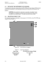
Figure 2-3 Re mov ing/Re plac ing the RS485 Op tion PCB
or Re mote Re set Op tion PCB