


SM067-3 November, 2000 3-4
59039
1
8
-DIN Digi tal In di ca tor Sec tion 3
Prod uct Man ual - Vol ume II Con figu ra tion Mode
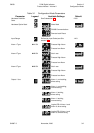
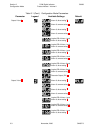
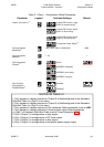
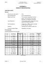
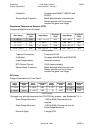
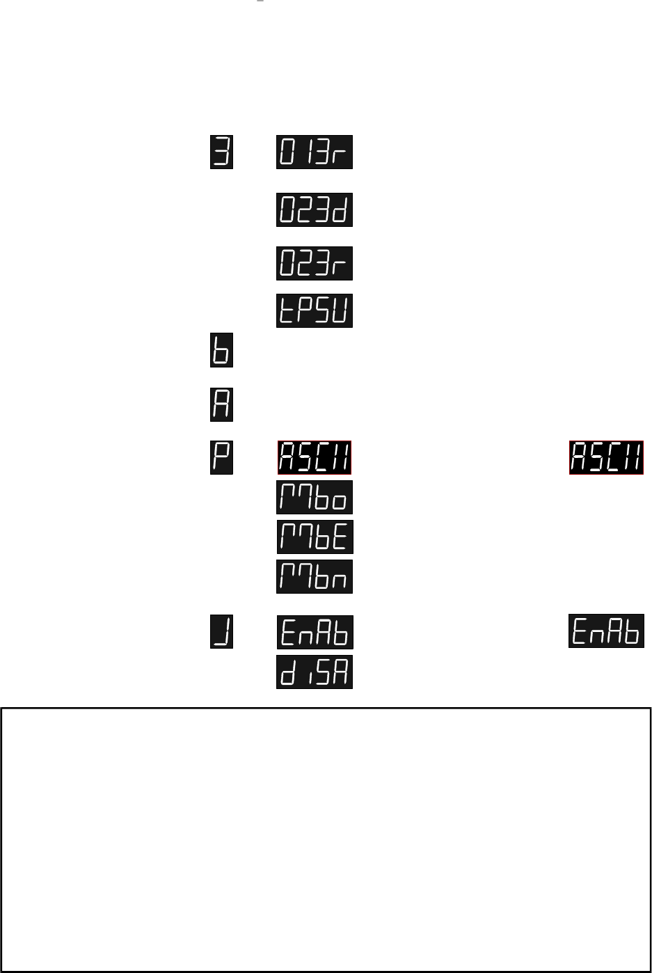
Table 3-1 (Cont.) Configuration Mode Parameters
Parameter
Output 3 Use (cont.)
2
Communications
Baud Rate
3
Communications
Address
3
Communications
Protocol
3
Cold Junction
Compensation
Enable/Disable
4
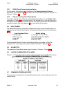
Legend Available Settings
Logical OR of Alarm 1 and
Alarm 3, reverse-acting
7
Logical OR of Alarm 2 and
Alarm 3, direct-acting
7
Logical OR of Alarm 2 and
Alarm 3, reverse-acting
7
Transmitter Power Supply
8
1200, 2400, 4800 or 9600 Baud
1 - 32
ASCII
MODBUS, odd parity
MODBUS, even parity
MODBUS, no parity
Enabled
Disabled
Default
4800
1
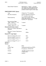
NOTES ON TABLE 3-1
1. Only appears in display sequence if Output 2 is fitted/configured in the Hardware
Definition Code (i.e. Digit 3 is non-zero).
2. Only appears in display sequence if Output 3 is fitted/configured in the Hardware
Definition Code (i.e. Digit 4 is non-zero).
3. Only appears in display sequence if the Hardware Option parameter is set to r485.
4. Only appears in display sequence if thermocouple input is fitted/configured
i.e. Digit 1 of Hardware Definition Code is set to 2 (see Subsection 3.2)
5. Only if Output 2 is configured as a relay output
6. Only if Output 2 is configured as a DC linear output
7. Only if Output 3 is configured as a relay output
8. Only if Output 3 is configured as a transmitter power supply output