


SEC TION 2
INTERNAL LINKS AND SWITCHES
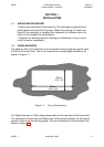
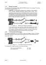
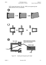
2.1 REMOVING THE INSTRUMENT FROM ITS HOUSING
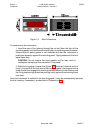
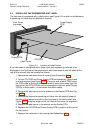
To withdraw the instrument from its housing, simply grip the side edges of the front
panel (there is a finger grip on each edge) and pull the instrument forwards. This will
release the instrument from its rear connectors in the housing and will give access to
the PCBs. Take note of the orientation of the instrument for subsequent replacement
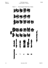
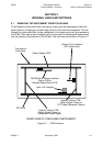
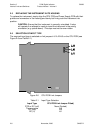
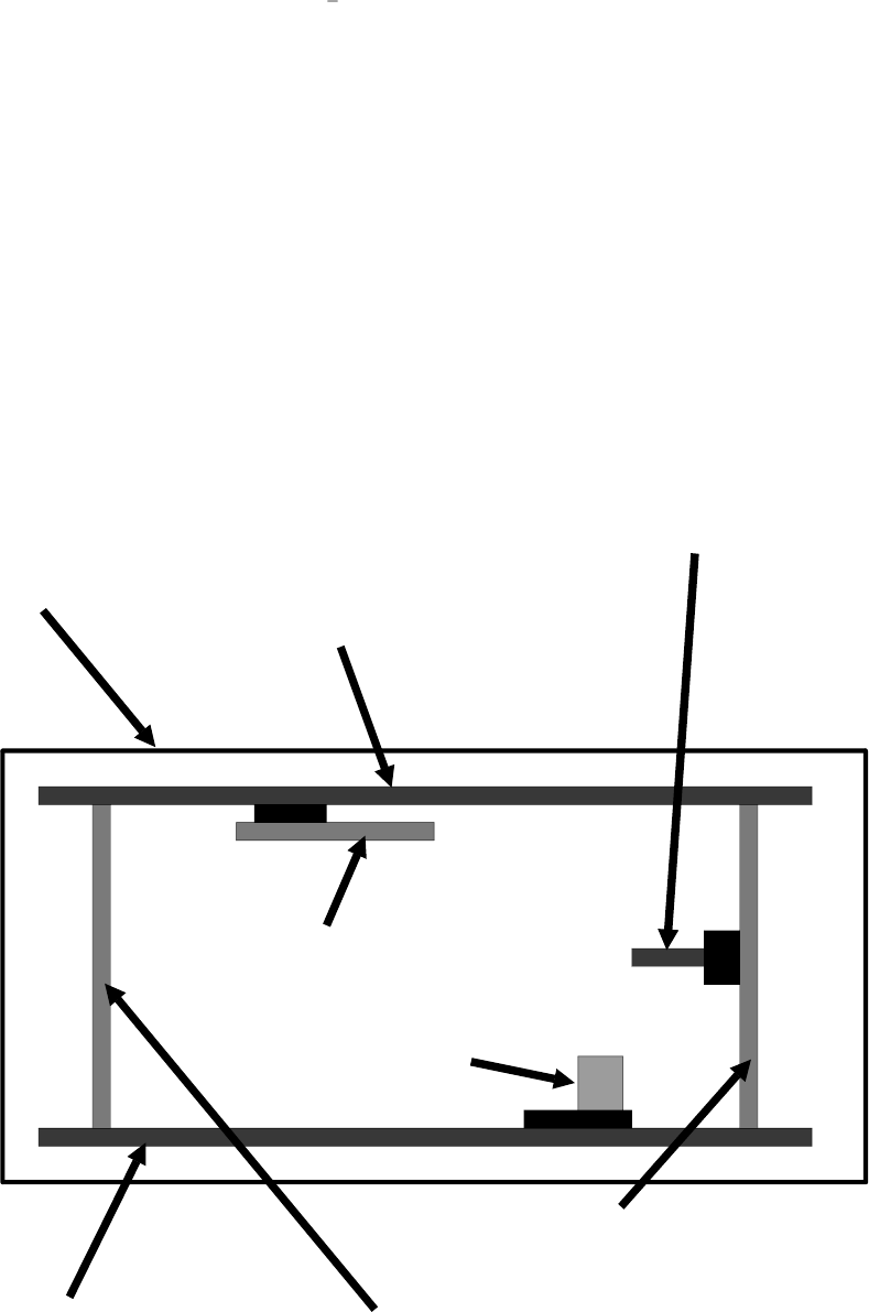
into the housing.The positions of the PCBs in the instrument are shown in Figure 2-1.
SM067-2 November, 2000 2-1
59039
1
8
-DIN Digi tal In di ca tor Sec tion 2
Prod uct Man ual - Vol ume II In ter nal Links and Switches
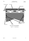
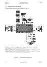
Figure 2-1 PCB Po si tions
Power Supply PCB
RS485 Serial Communications
Option PCB or
Remote Reset Option PCB
Output 3 Option PCB -
Relay Output (Alarm) or
Transmitter Power Supply
CPU PCB
Output 2 Option PCB -
Relay Output (Alarm) or
DC Output (Recorder Output)
Output 2 Link Jumpers
(DC Output only)
REAR VIEW OF UNHOUSED INSTRUMENT
Top edge of
front panel
Input Link Jumpers