


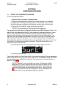
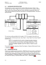
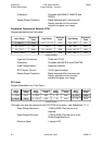
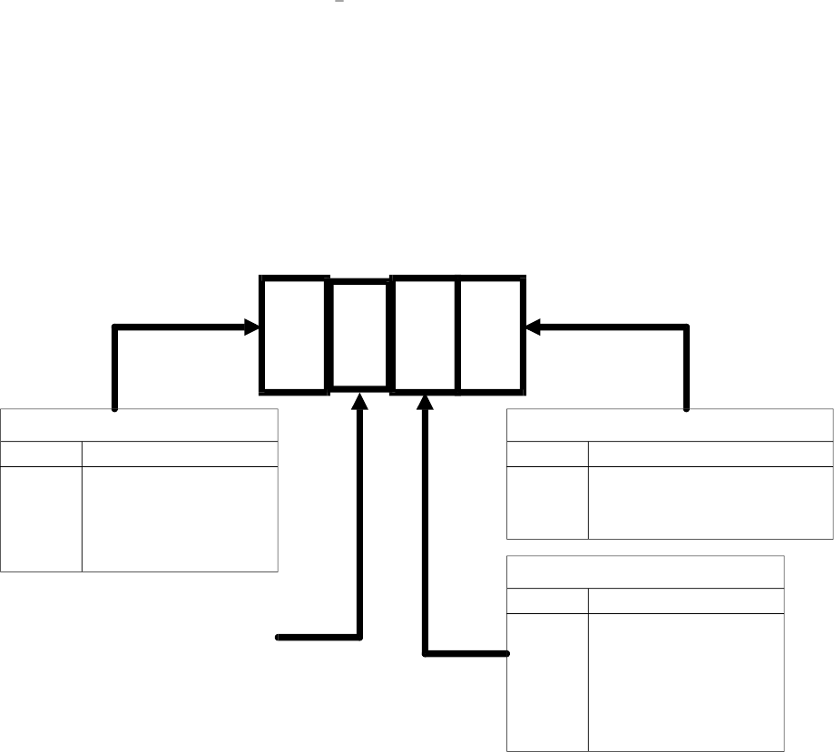
3.2 HARDWARE DEFINITION CODE
This parameter is used to represent the hardware fitted (input type, Output 1 type,
Output 2 type and Output 3 type); this must be compatible with the hardware actually
fitted. Access to the Hardware Definition Code is gained by pressing the Scroll and
Lower keys simultaneously whilst the instrument is in Configuration Mode. The code is
used as follows:
The maximum setting available for this code is 4178. For example, the code for an
instrument with a thermocouple input, relay Output 1, relay Output 2 and relay Output 3
would be 2111.
NOTE: It is essential that this code is changed promptly whenever
there is a change to the instrument’s hardware configuration (change
of input/output type, alarm/recorder output added/removed etc.). The
instrument software depends upon this code to ensure correct
operation.
This code may also be viewed as a Read Only display in Operator Mode (see Volume
1, Subsection 2.9).
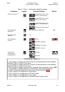
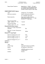
3.3 HARDWARE OPTION
There are two hard ware op tions avail able - RS485 Se rial Com mu ni ca tions and Re mote
Latch ing Alarm Re set. These op tions are mu tu ally ex clu sive. Ac cess is gained to the
Hard ware Op tion pa rame ter by press ing the Scroll key whilst the Hard ware Defi ni tion
Code is dis played in Con figu ra tion Mode. The Hard ware Op tion dis play may be viewed
as a Read Only dis play in Op era tor Mode (see Vol ume 1, Sub sec tion 2.9)
3-5 November, 2000 SM067-3
Sec tion 3
1
8
-DIN Digi tal In di ca tor 59039
Con figu ra tion Mode Prod uct Man ual - Vol ume II
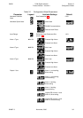
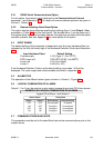
Digit 1 - Input Type
Value
1
2
3
4
Meaning
RTD/Linear DC (mV)
Thermocouple †
Linear DC (mA)
Linear DC (V)
Meaning
Not fitted †
Relay
DC (0 - 10V)
DC (0 - 20mA)
DC (0 - 5V)
DC (4 - 20mA)
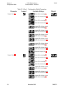
Digit 3 - Output 2 Type
Value
0
1
3
4
5
7
Meaning
Not fitted †
Relay
Transmitter Power Supply
Digit 4 - Output 3 Type
Value
0
1
8
† Default setting
1
Output 1 always
relay output