


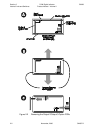
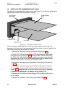
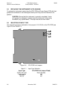

2.5 REPLACING THE INSTRUMENT IN ITS HOUSING
To replace the instrument, simply align the CPU PCB and Power Supply PCB with their
guides and connectors in the housing and slowly but firmly push the instrument into
position.
CAUTION: Ensure that the instrument is correctly orientated. A stop
will operate if an attempt is made to insert the instrument in the wrong
orientation (e.g. upside-down). This stop must not be over-ridden.
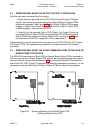
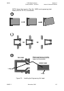
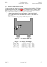
2.6 SELECTION OF INPUT TYPE
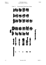
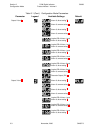
The required input type is selected on link jumpers LJ1/LJ2/LJ3 on the CPU PCB (see
Figure 2-6 and Table 2-1).
2-6 November, 2000 SM067-2
Sec tion 2
1
8
-DIN Digi tal In di ca tor 59039
In ter nal Links and Switches Prod uct Man ual - Vol ume II
Figure 2-6 CPU PCB Link Jump ers
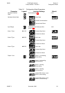
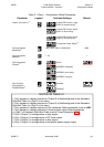
Table 2-1 In put Type Se lec tion
Input Type
RTD or DC (mV)
Thermocouple
DC (mA)
DC (V)
CPU PCB Link Jumper Fitted)
None (Parked)
LJ3
LJ2
LJ1