


OM067-4 November, 2000 4-3
59039
1
8
-DIN Digi tal In di ca tor Sec tion 4
Product Man ual - Vol ume I RS485 Se rial Com mu ni ca tions
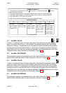
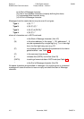
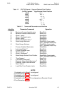
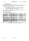
Table 4-1 {DATA} Ele ment - Sign and Deci mal Point Po si tion
+abcd
+abc.d
+ab.cd
+a.bcd
–abcd
–abc.d
–ab.cd
–a.bcd
{DATA} Content
abcd0
abcd1
abcd2
abcd3
abcd5
abcd6
abcd7
abcd8
Sign/Decimal Point Position
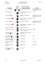
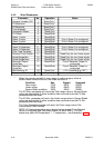
Table 4-2 Com mands/Pa rame ters and Iden ti fi ers
Identifier
Character
A
B
C
D
E
F
G
H
J
L
M
N
O
Q
T
Z
[
\
]
m
Parameter/Command
Maximum Process Variable value
Minimum Process Variable value
Alarm 1 value
Alarm 1 Hysteresis value
Alarm 2 value
1
Alarm 2 Hysteresis value
1
Scale Range Maximum
Scale Range Minimum
Process Variable Offset value
Instrument Status
2
Process Variable value
Alarm 3 value
3
Alarm 3 Hysteresis
3
Scale Range Decimal Point Position
Time Elapsed
Instrument Commands
4
Recorder Output Scale Maximum
5
Recorder Output Scale Minimum
5
Scan Table
6
Input Filter Time Constant value
NOTES
1. Applicable only if Alarm 2 is configured.
2. See Subsection 4.3.15.
3. Applicable only if Alarm 3 is configured.
4. See Subsection 4.3.16.
5. Applicable only if Output 2 is configured as a Recorder Output.
6. See Subsection 4.3.17.
Operation
Read Only
Read Only
Read/Write
Read/Write
Read/Write
Read/Write
Read/Write (linear inputs
only) - otherwise Read Only
Read/Write (linear inputs
only) - otherwise Read Only
Read/Write
Read Only
Read Only
Read/Write
Read/Write
Read/Write (linear inputs
only) - otherwise Read Only
Read Only
Write Only
Read/Write
Read/Write
Read Only
Read/Write