


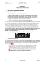
2.4 INSTALLING THE ENGINEERING UNIT LABEL
The instrument is equipped with a label carrier (see Figure 2-4) to which a self-adhesive
engineering unit label may be attached if required.
If the instrument is configured with a linear input and engineering units are to be
displayed on the front panel, the required unit label (see sheet of peel-off labels at the
rear of this manual) may be installed as follows:
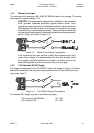
1. Re move the in stru ment from its hous ing (see Sub sec tion 2.1).
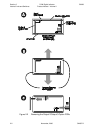
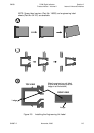
2. For the CPU PCB and Power Sup ply PCB si mul ta ne ously, gen tly bend
one re tain ing arm (see Fig ure 2-5A) to free one side of each PCB; swing
the PCBs clear of the front panel and care fully move them away from the
front panel (the CPU PCB will still be con nected to the front panel/Dis play
PCB by a rib bon ca ble - do not stress this rib bon ca ble ).
3. Re move the la bel car rier from its ap er ture in the Dis play PCB (see Fig -
ure 2-5B).
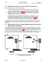
4. Re move the re quired en gi neer ing unit la bel from the peel- off sheet at
the rear of this man ual and af fix to the front face of the la bel car rier (see
Fig ure 2-5C), us ing the ledge on the front face of the car rier for align ment.
5. Re place the la bel car rier in its ap er ture on the Dis play PCB.
6. Re place the CPU PCB and Power Sup ply PCB in po si tion at the rear of
the front panel.
7. Re place the in stru ment in its hous ing (see Sub sec tion 2.5).
2-4 November, 2000 SM067-2
Sec tion 2
1
8
-DIN Digi tal In di ca tor 59039
In ter nal Links and Switches Prod uct Man ual - Vol ume II
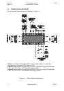
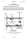
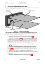
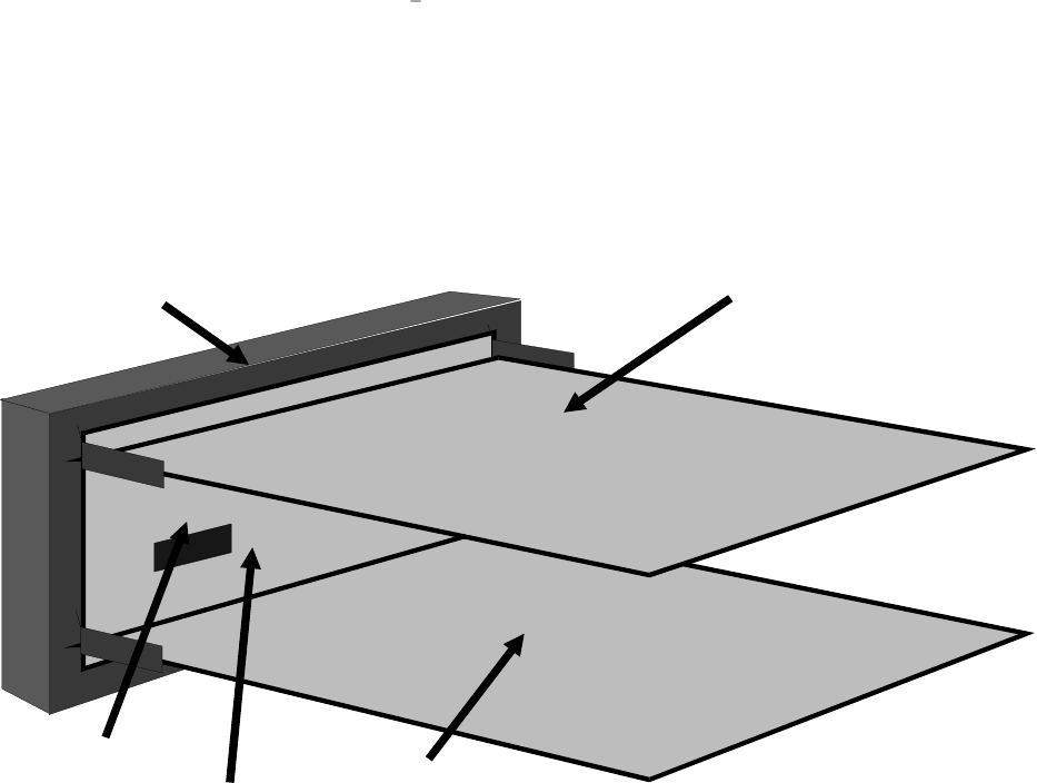
Figure 2-4 Lo ca tion of La bel Car rier
Front Panel
(top edge)
Power Supply
PCB
CPU PCB
Display PCB
Label Carrier