


3.3.1 RS485 Se rial Com mu ni ca tions Op tion
For this option, the protocol used is defined by the Communications Protocol
parameter - see Subsection 3.9. Full details of communications operation are given in
Volume 1, Section 4.
3.3.2 Re mote Latch ing Alarm Re set Op tion
This option has the same effect as resetting the latching Alarm 1 (see Output 1 Use
parameter in Table 3-1) from the front panel. The latched Alarm 1 can be reset only if
the original alarm condition has been cleared; this reset has no effect whilst the alarm
condition prevails. See also Appendix A for more details of this option.
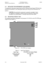
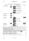
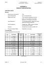
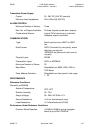
3.4 INPUT RANGE
The default setting of this parameter is dependent upon the input hardware fitted, as
indicated by the first (left-most) digit of the Hardware Definition Code (see Subsection
3.2):
If the Hardware Definition Code is at its default setting, input code 1419 will be
displayed. The input ranges and codes available are listed in Appendix A.
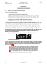
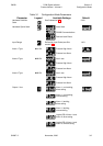
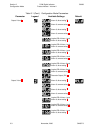
3.5 ALARM TYPE
The operation of the different alarm types is shown in Volume 1, Figure 3-1.
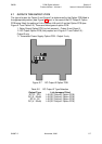
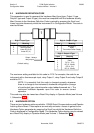
3.6 LOGICAL COMBINATION OF ALARMS
Output 1, 2 or 3 may be used as a relay output representing a logic OR of two alarms.
3.7 COMMUNICATIONS BAUD RATE
This pa rame ter must be set to the same Baud rate as the com mu ni ca tions port on the
mas ter de vice.
SM067-3 November, 2000 3-6
59039
1
8
-DIN Digi tal In di ca tor Sec tion 3
Prod uct Man ual - Vol ume II Con figu ra tion Mode
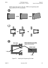
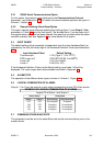
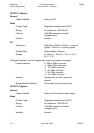
EXAMPLE OF LOGICAL COMBINATION OF ALARMS
Logical OR of Alarm 1 with Alarm 2
Alarm Status
Alarm 1
OFF
ON
OFF
ON
Direct-acting
De-energised
Energised
Energised
Energised
Alarm 2
OFF
OFF
ON
ON
Reverse-acting
Energised
De-energised
De-energised
De-energised
Relay State
Input Hardware Fitted
Thermocouple
RTD/Linear mV)
Linear mA
Linear V
Default Setting
1419 (Type “J”, 0 to 761
o
C)
7220 (RTD Pt100, 0 to 800
o
C)
3414 (4 to 20mA)
4446 (0 to 10V)