


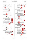
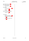

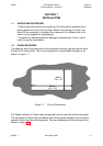
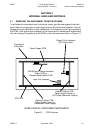
1.3 CONNECTIONS AND WIRING
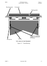
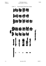
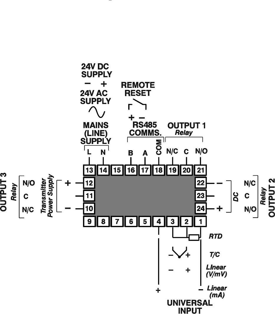
The rear terminal connections are illustrated in Figure 1-4.
1-4 November, 2000 SM067-1
Sec tion 1
1
8
-DIN Digi tal In di ca tor 59039
In stal la tion Prod uct Man ual - Vol ume II
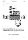
Figure 1-4 Rear Ter mi nal Con nec tions
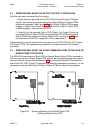
Output 1 is always a relay output which may be used as Alarm 1 (latching or
non-latching) or the logical OR of Alarms 1 & 2.
Output 2 (option) may be a relay output (Alarm 2, Alarm 3 or logical OR of Alarms
1 & 2, 1 & 3 or 2 & 3) or a DC output (recorder output)
Output 3 (option) may be a relay output (Alarm 2, Alarm 3 or logical OR of Alarms
1 & 2, 1 & 3 or 2 & 3) or a transmitter power supply output