


L {N} {P} {DATA} I *
(where I = Hex 49) indicating that the instrument is ready to implement the command. If
the parameter specified is invalid or is not modifiable or if the desired value is outside
the permitted range for that parameter, the instrument replies with a negative
acknowledgement in the form:
L {N} {P} {DATA} N *
4.2.4 Type 4 Mes sage
L {N} {P} I *
This type of message is sent by the master device to the addressed slave following a
successful Type 3 message transmission and reply to/from the same slave instrument.
Provided that the {DATA} content and the parameter specified in the preceding Type 3
message are still valid, the slave will then set the parameter to the desired value and
will reply in the form:
L {N} {P} {DATA} A *
where {DATA} is the new value of the parameter. If the new value or parameter
specified is invalid, the slave will reply with a negative acknowledgement in the form:
L {N} {P} {DATA} N *
where {DATA} is indeterminate. If the immediately-preceding message received by the
slave was not a Type 3 message, the Type 4 message is ignored.
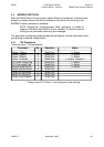
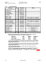
4.3 INDIVIDUAL PARAMETERS
The individual parameters and how they may be interrogated/modified are described
below. Unless otherwise stated, the {DATA} element will follow the standard five-digit
format and the decimal point position must be correct for the new value to be accepted
and for modification to occur.
NOTE: The communications identifier character {P} for each
parameter is shown to the right of each subsection heading.
4.3.1 Proc ess Vari able {P} = M
This parameter may be interrogated only, using a Type 2 message. If the process
variable is out of range, the five-digit {DATA} field in the reply will not contain a number,
but will contain <??>0 (over-range) or <??>5 (under-range).
4.3.2 Proc ess Vari able Off set {P} = J
This parameter may be modified/interrogated using a Type 2 message or a Type 3/4
message sequence. It modifies the actual process variable value (as measured at the
instrument’s input terminals) in the following manner:
Modified PV value = Actual PV value + process variable offset value
The modified PV value is limited by Range Maximum and Range Minimum and is used
for display and alarm purposes and for recorder outputs.
OM067-4 November, 2000 4-5
59039
1
8
-DIN Digi tal In di ca tor Sec tion 4
Product Man ual - Vol ume I RS485 Se rial Com mu ni ca tions