


164 APPENDIX D: CONNECTORS AND CABLES
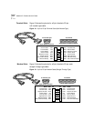
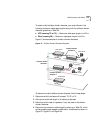
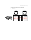
Terminal Cable Figure 18 shows the pinouts for a 9-pin female to 25-pin
null modem-type cable.
Figure 18 9-pin to 25-pin Terminal Cable (Null Modem-Type)
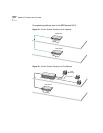
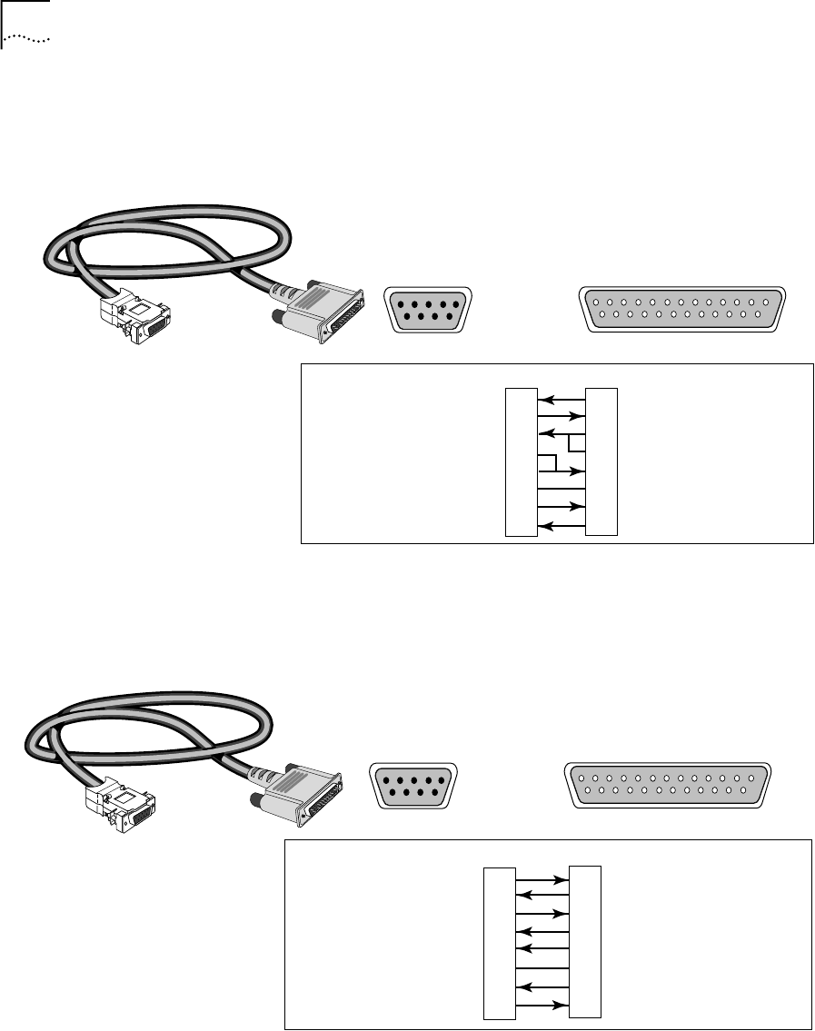
Modem Cable Figure 19 shows the pinouts for a 9-pin female to 25-pin male
straight-through-type cable.
Figure 19 9-pin to 25-pin Modem Cable (Straight-Through-Type)
1 2 3 4 5 6 7 8 9 10 11 12 13
14 15 16 17 18 19 20 21 22 23 24 25
5 4 3 2 1
9 8 7 6
Name Abbr Pin Pin Abbr Name
25-pin male or female connector
9-pin female connector
2
3
1
8
7
5
4
6
2
3
4
5
8
7
6
20
TxD
RxD
RTS
CTS
CD
GND
DSR
DTR
RxD
TxD
CD
CTS
RTS
GND
DTR
DSR
Transmit Data
Receive Data
Request to Send
Clear to Send
Carrier Detect
Signal Ground
Data Set Ready
Data Terminal Ready
Receive Data
Transmit Data
Carrier Detect
Clear to Send
Request to Send
Signal Ground
Data Terminal Ready
Data Set Ready
To Console port
To terminal
1 2 3 4 5 6 7 8 9 10 11 12 13
14 15 16 17 18 19 20 21 22 23 24 25
5 4 3 2 1
9 8 7 6
25-pin male connector
9-pin female connector
To Console port
To modem
Name Abbr Pin Pin Abbr Name
2
3
4
8
5
7
6
20
Transmit Data
Receive Data
Request to Send
Carrier Detect
Clear to Send
Signal Ground
Data Set Ready
Data Terminal Ready
TxD
RxD
RTS
CD
CTS
GND
DSR
DTR
TxD
RxD
RTS
CD
CTS
GND
DSR
DTR
Transmit Data
Receive Data
Request to Send
Carrier Detect
Clear to Send
Signal Ground
Data Set Ready
Data Terminal Ready
3
2
7
1
8
5
6
4