4-20 C
HAPTER
4: M
ANAGING
T
HE
S
WITCH
1000
Configuring Resilient Links
With the Switch Management screen displayed,
choose the port that will be set up as the main
port in the resilient link pair, then select the RESIL-
IENCE button.
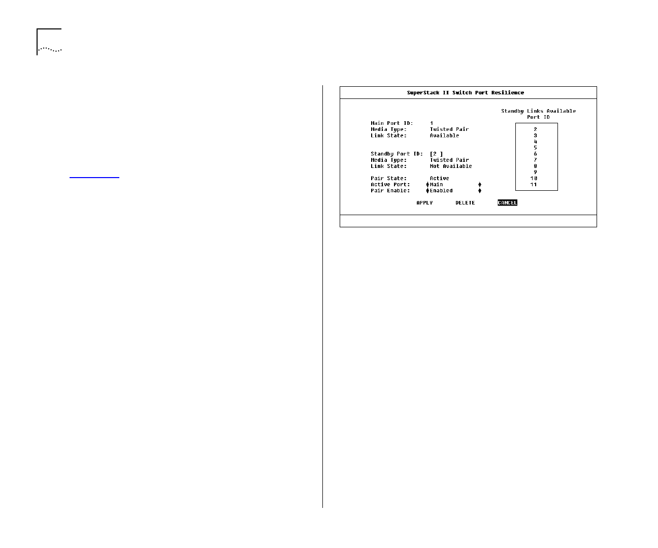
The Port Resilience screen is displayed as shown in
Figure 4-14
. This screen allows you to setup, edit
and delete resilient link pairs.
The screen shows the following:
Main Port ID
This read-only field shows the ID of
the main port.
Media Type
Twisted Pair / Fiber
This read-only field
shows the media type connected to the main port.
Link State
Available / Not Available / Not Present
This read-only field shows the connection state of
the main port:
■
Available
— The port is operating normally
■
Not Available
— The resilient link pair is disabled
■
Not Present
— The port is not present in the cur-
rent hardware
Standby Port ID
This field shows the current
standby port ID and allows you to enter a new port
ID. The standby port must be in the same VLAN as
the main port.
Media Type
Twisted Pair / Fiber
This read-only field
shows the standby port media type.
Figure 4-14
Port Resilience screen
Link State
Available / Not Available / Not Present
This read-only field shows the connection state of
the standby port:
■
Available
— The port is operating normally
■
Not Available
— The resilient link pair is disabled
■
Not Present
— The port is not present in the cur-
rent hardware
Standby Links Available
This listbox shows the
ports that you can configure as standby.
Pair State
Active / Both Failed / Unknown /
Not Available
This read-only field shows the current
operating state of the resilient link pair:
■
Active
— The resilient link pair is enabled and
operating normally with both main and standby
port capable of carrying traffic.


