


16 CHAPTER 2: INSTALLING THE V7122 MEDIA GATEWAYS
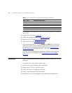
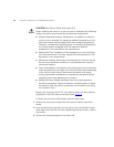
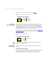
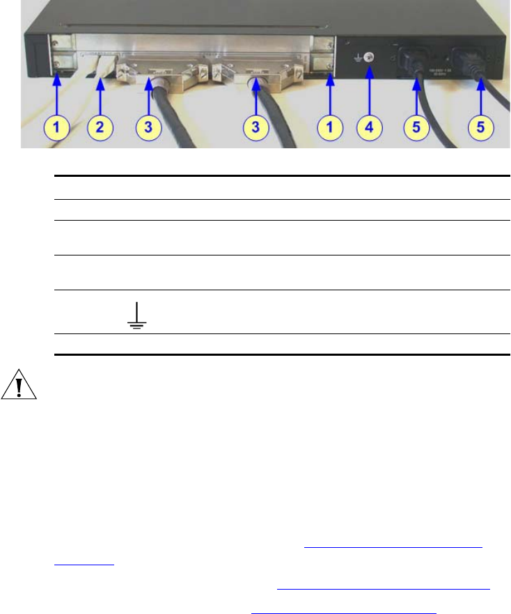
Figure 4 V7122 (16 Trunks, Dual AC Power H/W Configuration) Rear-Panel
Cabling
CAUTION: Electrical Earthing
The unit must be permanently connected to earth using the screw
provided on the rear panel. Use 14-16 AWG wire and a proper ring
terminal for the earthing.
To cable the V7122, perform these steps:
1 Permanently connect the device to a suitable earth with the protective
earthing screw on the rear panel, using 14-16 AWG wire.
2 Connect the E1/T1 trunk interfaces (see Connecting the E1/T1 Trunk
Interfaces).
3 Install the Ethernet connection (see Installing the Ethernet Connection).
4 Connect the power supply (see Connecting the Power Supply).
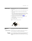
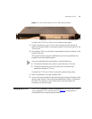
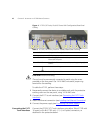
Connecting the E1/T1
Trunk Interfaces
Connect the V7122 E1/T1 Trunk interfaces using either Telco (V7122 with
16 spans) or RJ-48 (V7122 with 1, 2, 4, or 8 spans) connectors, as
described in the procedure below:
Table 3 V7122 (16 Trunks, Dual AC Power) Rear-Panel Cabling
Item Label Component Description
1 -- RTM locking screws.
2 ETHERNET Two Category 5 network cables, connected to the two
Ethernet RJ-45 ports.
3 TRUNKS Two 50-pin Telco connector cables, each supporting eight
trunks.
4 Protective earthing screw.
5 100-240~1.5A Dual AC power cables.