


Cabling the V7122 17
To connect E1/T1 trunk interface using 50-pin Telco connectors (16-trunk
device), perform these steps:
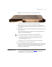
1 Attach the Trunk cable with a 50-pin male Telco connector to the 50-pin
female Telco connector labeled Trunks 1-->8 on the Rear Transition
Module (RTM).
2 Connect the other end of the Trunk cable to the PBX/PSTN switch.
3 Repeat steps 1 and 2 for the other Trunk cable, but this time connect it to
the connector labeled Trunks 9-->16.
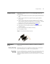
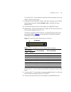
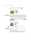
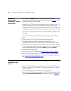
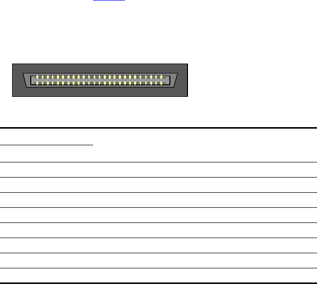
The 50-pin male Telco cable connector must be wired according to the
pinouts described in
Table 4, and to mate with the female connector
illustrated in the figure below.
Figure 5 50-pin Female Telco Board-Mounted Connector
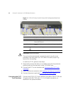
To connect E1/T1 trunk interface using RJ-48c connectors, perform these
steps:
1 Connect the E1/T1 trunk cables to the ports labeled Trunks 1 to 8 (in the
case of the 8-trunk device) on the V7122 RTM.
2 Connect the other ends of the Trunk cables to the PBX/PSTN switch.
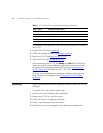
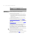
Table 4 E1/T1 Connections on each 50-pin Telco Connector
E1/T1 Number
Tx Pins (Tip/Ring) Rx Pins (Tip/Ring)
1 to 8 9 to 16
1 9 27/2 26/1
2 10 29/4 28/3
3 11 31/6 30/5
4 12 33/8 32/7
5 13 35/10 34/9
6 14 37/12 36/11
7 15 39/14 38/13
8 16 41/16 40/15
125
26
50
Pin Numbers