


38 CHAPTER 6: MONITORING THE V7122 MEDIA GATEWAYS
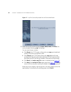
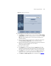
On the front panel, 16 LEDs are provided for 16-span units and 8 LEDs
are provided for 1-span, 2-span, 4-span, and 8-span units. In the case of
1-, 2-, and 4-span units, the extra LEDs are unused.
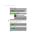
During correct V7122 operation, the ACT LED is lit green and the FAIL
LED is off.
-- Normal operation
ACT Green Gateway initialization sequence terminated OK Bi-color
LED
Yellow N/A
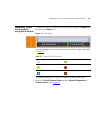
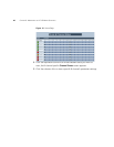
Table 9 E1/T1 Trunk Status LEDs Description
Label Color Description
T1/E1 Status 1 to 8
and
T1/E1 Status 9 to 16
Green Trunk is synchronized (normal
operation)
Bi-color
LED
Red Loss due to any of the following 4
signals
LOS Loss of Signal
LFA Loss of Frame Alignment
AIS Alarm Indication Signal (the Blue Alarm)
RAI Remote Alarm Indication (the Yellow Alarm)
Table 10 Ethernet LEDs Description
Label LED Description
LINK Green Link all OK
ACT Yellow Transmit / receive activity
Table 11 cPCI LED Indicators
Label LED Description
PWR Green Power is supplied to the board
SWAP READY Blue The cPCI board can now be removed.
The cPCI board was inserted successfully.
Table 8 Status LEDs Description
Label Color Description