


Connect Cables
4 MM701G and MM702G User Manual
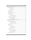
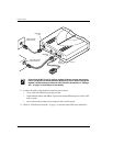
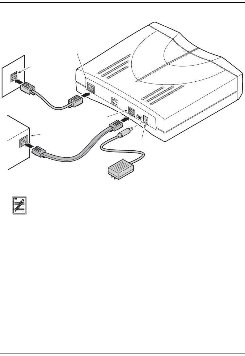
2 Connect the cables to the modem rear panel as shown above:
• silver cable to the DSL line port and wall jack
• black Ethernet cable to the 10Base-T port and to another Ethernet device such as a PC,
hub, or router
• power cable to the modem power connector and to facility power
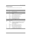
3 Refer to “LED Status Indications” on page 5, to check modem LED status indications.
Ensure that the NIC in the PC and the modem LAN port are both set to either
half- or full-duplex for the transmission direction(s). If you need to change the
modem LAN port setting to match the NIC, follow the procedures in “Manage
DSL” on page 118 (half-duplex is the default).
Wall jack with
DSL service
DSL LINE
POWER
DSL line
port
Power
connector
M
D
I
M
D
I-X
10BASE-T
CONSOLE
PC, hub or other
network device
10Base-T
port
M0152-B