


Appendix B: Specifications
MM701G and MM702G User Manual 143
Connector Pinouts
The following sections provide the pinout information for the various modem connectors.
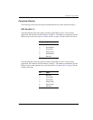
DSL Port (RJ-11)
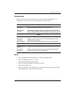
The following table shows the signal on each pin of the DSL port for a 2-wire G.shdsl
application. The connector for this interface is an RJ-11. The modem accommodates Tip and
Ring reversal on this one loop. See “Connect Cables” on page 3 for the location of this port.
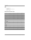
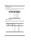
The following table shows the signal on each pin of the DSL port for a 4-wire G.shdsl
application. The connector for this interface is an RJ-11. The modem accommodates Tip and
Ring reversal on each separate Loop A and Loop B. See “Connect Cables” on page 3 for the
location of this port.
Pin Signal
1 Not used
2 No connection
3 Tip (Loop A)
4 Ring (Loop A)
5 No connection
6 Not used
Pin Signal
1 Not used
2 Tip (Loop B)
3 Tip (Loop A)
4 Ring (Loop A)
5 Ring (Loop B)
6 Not used