


10 General Information
Accessories
Agilent No. Description
34551A Rack mount for Agilent 66001A MPS keyboard
Description
The Agilent 66lxxA Series Power Modules are used in the Agilent 66000 Modular Power System (MPS) mainframe to
provide a range of dc output voltages and currents. The modules are installed or removed from the front of the mainframe
without the need for disconnecting any wires. Modules may be connected in series or parallel to provide increased output
voltages or currents. The modules can be equipped with optional isolation and polarity reversal relays that are built into the
module output connector.
The power module front panel has digital readouts of output voltage and current. It also has annunciators that indicate:
• constant voltage, constant current, or unregulated operation
• activation of a protection circuit
• disabling of the output
• remote operation (addressed by the controller)
Programming
The power module is programmed over the GPIB from a controller using SCPI (Standard Commands for Programmable
Instruments). This makes power module programs compatible with those of all other instruments controlled with this
language. Among the functions that can be programmed are output voltage and current, OVP (overvoltage protection),
OCP (overcurrent protection), status registers, output relays, and output voltage and current calibration.
In addition, the power module has programmable trigger, list, and RI/DFI (remote inhibit/discrete fault indicator)
subsystems. Triggers can occur from signals at the mainframe TRIG IN jack or from selected internal events. The list
subsystem generates preprogrammed sequential outputs in response to triggers. The RI/DFI subsystem generates an output
on the mainframe FLT line in response to selected internal events or turns off the output in response to an input on the
mainframe INH line.
The power module also can be programmed locally from the optional Agilent 66001A MPS Keyboard. The keyboard has
an alphabetical command menu for all power module SCPI commands. By scrolling through the menu and entering the
appropriate parameters, commands may be created for development or debugging.
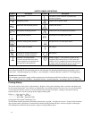
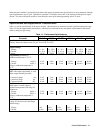
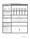
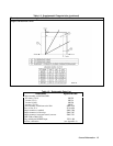
Output Characteristic
The power module can operate in either CV (constant voltage) or CC (constant current) mode over its voltage and current
output range (see Table 1-1). The operating locus (see Output Characteristic Curve in Table 1-2) shows a single-range,
limited two-quadrant capability. The operating point is determined by the voltage setting (V
S
), the current setting (I
S
) and
the load impedance (R
l
). Two operating points are shown. Point 1 is defined by the load line cutting the operating locus in
the CV region, which defines the CV mode (curve A). In this mode, the power module will maintain the voltage at V
S
for
varying load currents (determined by V÷R
l
) up to I
S
. If the load demands a current greater than I
S
, the power module
switches to CC mode. CC mode (curve B) is defined by the load line cutting the operating locus in the CC region (see Point
2). Under this condition, the power module maintains the current at I
S
at some voltage determined by I
S
x R
l
.