


Index 51
Index
A
address slot, 20
ampere capacity, 21
annunciators, display panel
Addr, 27
CC, 27
Dis, 27
Prot, 27
Unr, 27
C
cables
GPIB, 15
serial link, 15
calibrating current, 37
calibrating voltage, 36
calibration, 35
constants, 38
equipment for, 36
password, 35, 38
program for, 39
verification of, 35
capacitive loads, 26
CC mode, 11
checkout, output, 28
checksum error, 28
commands (see SCPI)
commands, common, 46, 50
commands, subsystem, 46, 50
connector, FLT/INH, 34
connector, output, 21, 22, 25, 29
controller, GPIB, 31
CV mode, 11
D
default state (see power-on state)
DFI
description of, 1-2
digital connector pins for (see Chapter 3 in
Installation Guide)
examples of use , 34
OUTP:DFI commands for (see Chapter 3 in
Programming Guide)
signal electrical characteristics (see Chapter 1 in
Installation Guide)
status parameter links for (see Chapter 3 in
Programming Guide)
SUM3 status bit for (see Chapter 4 in Programming
Guide)
display panel, 27
downprogramming, 11
E
EEPROM, 30
error messages, display panel
calibration, 38
runtime, 30
selftest, 30
system, 30
error messages, keyboard, 49
F
factory-default state, 18
fault indicator (see FLT)
fixed-mode operation, 28, 32
FLT input (see DFI)
fuse, line, 15, 18, 29
G
ground, earth, 9, 21
ground, signal, 21
GPIB address
changing, 26
determining, 26
primary, 26
subaddress, 26, 42
GPIB capabilities, 14
H
hardware, 15
I
identification, module, 9
impedance, output, 11
indicators, display panel
AMPS, 27
VOLTS indicator, 27
inductive loads, 26
INH (see RI)
initiating triggers, 33
isolation, 32
K
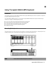
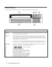
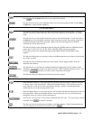
keyboard, 41
keyboard annunciators
Cal, 42
Dis, 42
Err, 42