


Installation 17
2
Installation
Inspection
Damage
When you receive your power module, inspect it for any obvious damage that may have occurred during shipment. If there
is damage, notify the shipping carrier and the nearest Agilent Sales and Support Office immediately. Warranty information
is printed in the front of this guide.
Items Supplied
In addition to this manual, check that the following items are included with each power module (see Table 1-3 for part
numbers):
•
One output connector
•
One Series 66lxxA Programming Guide
•
One or more Manual Change Sheets may be included with each guide. If there are change sheets, make the
indicated corrections to the guides.
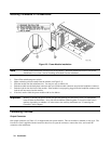
Switches
Before inserting the power module in the mainframe, read the following information to determine if you need to change any
of the switch settings.
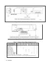
Line Voltage Switches
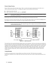
Figure 2-1 shows the location of the line voltage switches and the ac line fuse. The line voltage switches are shipped in
the 230-volt position. If required, use a flat-bladed screwdriver or similar tool to move both switches to the proper position
for your nominal line voltage.
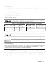
Line Voltage Switch Position
110, 120 Vac 115
200, 220, 230, 240 Vac 230
Note If you change the line switch position, remember to also correct the line voltage label on the rear of the
mainframe. The mainframe contains no line voltage switches.
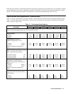
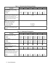
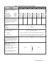
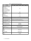
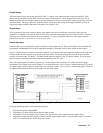
Configuration Switch
Figure 2-2 shows the location of the power module configuration switch. Table 2-1 indicates the functions of the switch and
the factory-default settings. If you need to change any of the settings, refer to the applicable function.