


Calibration 37
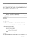
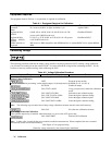
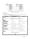
Figure A-1. Calibration Test Setup
Calibrating Current
The following procedure calibrates the output current. During the calibration, you will make two voltage measurements
across the output shunt and enter the computed current.
Table A-3. Current Calibration Procedure
Keyboard Entry Controller Entry † Function
OUTP OFF Disable the output
Connect the equipment as shown in Figure A-lB.
(Before proceeding, set the module output, via the keyboard or the GPIB, for 1.0 V at 0.5 A.)
OUTP ON Enable the output
CAL:STAT 1,66102 Using your password, enable the calibration
mode
CAL:CURR:LEV MIN Select the lower calibration point
Wait for the meter reading to stabilize. Then read the meter and enter the calculated current value.‡
CAL: CURR:DATA <NRf>
Enter lower current value
CAL:CURR:LEV MAX
Select the upper calibration point
Wait for the meter reading to stabilize. Then read the meter and enter the calculated current value.‡
CAL: CURR: DATA < NRf>
Enter the upper current value
Note: The following step overwrites the existing current calibration constants stored in nonvolatile memory.
CAL:SAV Save the new calibration constants
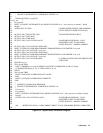
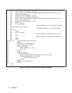
† See Figure A-2 for program listing.
‡ Calculate the current value as follows:
I=
V
R
R