


Turn-On Checkout 29
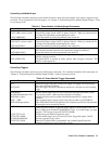
In Case Of Trouble
Mainframe Failure
You can assume there is a problem with the mainframe if there is more than one module in the mainframe and none of the
module fans are on. The trouble also is probably in the mainframe if the module fans are on and the their displays are
enabled (see "Configuration Switch" in "Chapter 2 - Installation") but their VOLTS and AMPS displays do not light. If a
module does not appear to be operating but its VOLTS and AMPS display light, move the module to another address slot.
If the above condition still occurs, then the problem probably is in the module.
Module Line Fuse
If a power module’s fan is on but its front panel does not light, the module line fuse may be blown. Proceed as follows:
1. Remove the power module from the mainframe.
Note You can remove and insert the power module without turning off the mainframe power provided the
module output is either disabled or is programmed to zero and there is no GPIB bus, trigger bus, or
RI/DFI activity. If you are in doubt, turn off the mainframe power.
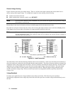
2. Check the line fuse (see Figure 2-1). If it is defective, replace it with one of the same type and rating (for the Agilent
part number, see Table 1-3).
Do not use a slow-blow fuse as a replacement.
3. Replace the power module in the mainframe.
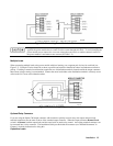
Module Output Connector
If the module panel indicates a normal voltage but there is no output at the load, the problem may be in the output
connector. This is even more probable if the connector has relays. The following tests may isolate the problem:
•
If another module is working normally, use its mainframe slot for the suspected module (be careful to guard against
any difference in module output voltage). If there is still no output, the problem is in the module. If the module has an
output in the new slot, the problem is with its original output connector.
•
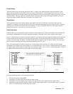
To check a suspected connector with a good module, proceed as follows (see DC Module Connectors Installation
Guide for details of the connector and its jumpers):
1. Disable the power module output (Dis annunciator on).
2. Remove the output connector from mainframe.
3. Examine the connector plug for bent pins.
4. Remove the cover from the output connector.
5. If there is no relay board, go to step 6. Otherwise, proceed as follows:
a. Remove the relay board by pulling it straight up.
b. Examine relay board connector for bent pins.
c. Examine the connector board to ensure that the required jumpers have been cut to enable relay
operation.
6. Examine the jumpers on the connector board. If any jumpers have been cut, they must be replaced.
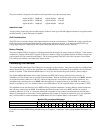
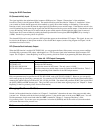
Error Messages
A power module may fail either during selftest or while operating (runtime). In either case, the module display may show
an error message indicating the reason for the failure.