


24 Installation
5. In order to maintain proper regulation, the load must always draw at least as much current as is programmed for the
module that is in CC mode. You can maintain regulation over a range of current only as long as this condition remains
true.
6. As near as is permitted by condition 5, program the current levels of both modules for a balanced distribution of the
total output current. Do not program the CV module near its maximum output current level.
7. Program the outputs of both modules ON.
8. When the system is operating, observe that the CV annunciator of the CV module stays on and the CC annunciator on
the CC module stays on. If not, repeat steps 1 through 7.
9. Once the modules are properly set up, do all subsequent voltage programming from the CV module; the CC
module will track that module.
Remember that although the CV module is controlling the output voltage, the CC module is
programmed to a slightly higher voltage. Do not allow the CC module to go into CV mode. Do not
program the CV module to 0 volts without first disabling the outputs of both power modules.
Otherwise, the CV module could sink up to 10% of its rated output current from the CC module.
As an example, assume that an Agilent 66102A (20 V @ 7.5 A) and an Agilent 66103A (35 V @ 4.5 A) are connected in
parallel to supply a load of 10 amperes at 18 volts. The Agilent 66102A is selected as CC mode module and will supply
approximately 7.6 A, maximum. The Agilent 66103A will be the CV module and will supply the remaining current (2.4 A).
When the two modules are operated in parallel, you may expect the system to regulate at 18 Volts and 10 amperes as long as
the load current remains above 7.6 amperes (see rule 5, above).
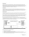
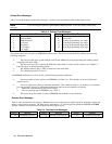
The following program shows how to program the two power modules. Generic code (SCPI commands) are shown; they
may be sent either from the keyboard or from a GPIB controller.
OUTP OFF Send to both modules
VOLT:LEV 18 Program the CV mode module
VOLT:PROT 18.5
CURR:LEV 2.4
VOLT:LEV 19 Program the CC mode module
VOLT:PROT 19.5
CURR:LEV MAX
OUTP ON Restore the outputs of both modules
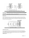
Series Operation
To prevent damage to the equipment, floating voltages must not exceed 240 Vdc. No output terminal
may be more than 240 V from chassis ground.
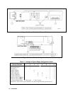
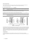
Figure 2-6 shows how the outputs of two power modules may be connected in series to increase the output voltage.
Connect only power modules that have the same maximum output current ratings. It is recommended that you set up
both modules to operate in CV mode with their current outputs equal to the full load current. If the external load is a
storage device, such as a battery or large capacitance, be careful how you shut down the system. For example, turning off
just one module could damage the remaining module by subjecting it to double its maximum output voltage from the storage
device.