


26 Installation
The power module is designed to be stable for load capacitances up to the following values:
Agilent 66101A 50,000
µ
F Agilent 66104A 4,500
µ
F
Agilent 66102A 20,000
µ
F Agilent 66105A 2,750
µ
F
Agilent 66103A 10,000
µ
F Agilent 66106A 1,650
µ
F
Inductive Loads
You may safely connect the power module output to inductive loads up to 100 mH. (Higher inductances are possible with a
modified module. Consult the factory for details.)
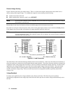
OVP Considerations
The OVP circuit senses the voltage at the output terminals, not at the sense terminals. Therefore the voltage sensed by the
OVP circuit can be significantly higher than the voltage being regulated at the load. You must program the OVP trip
voltage high enough to compensate for the expected drop from the power module output to the load.
Battery Charging
The power module OVP trip circuit has a downprogrammer that discharges the output whenever OVP trips. If the output is
connected to a battery and the OVP is tripped (or the power module voltage is programmed below the battery voltage), the
power module will sink current from the battery. The down programmer limits the value of this current to no more than
10% of the power module’s maximum rated output current.
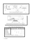
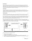
Connecting The Controller
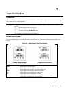
The Agilent 66000A Mainframe has a GPIB port for connection to the controller. Each power module has a GPIB primary
address determined by a switch on the mainframe, and a GPIB subaddress determined by the mainframe slot in which the
module is installed. If the mainframe GPIB address is set to 705, this becomes the power module’s primary address.
The Agilent 66000A Mainframe mode switch determines the IEEE 488 secondary addresses (also referred to as
subaddresses) of the modules that are installed in the mainframe. With the mainframe mode switch set to MAIN, modules
are assigned secondary addresses of 00 to 07, which correspond to the slot locations indicated on the mainframe. The
mainframe mode switch must be set to MAIN when the mainframe is connected directly to the GPIB. For example, if a
module is installed in slot 3 of a mainframe that is set to GPIB address 705, the complete address of the module is 70503.
The mainframe mode switch must be set to AUX (auxiliary) when the mainframe is serially-linked to another mainframe
that is directly connected to the GPIB. In mainframes that have the mode switch set to AUX, modules are assigned
secondary addresses of 08 to 15. Secondary address 08 corresponds to slot location 0 on the mainframe and secondary
address 15 corresponds to slot location 7 on the mainframe. For example, if a module is installed in slot 3 of a mainframe
that is serially linked to another mainframe at GPIB address 705, the complete address of the module is 70511.
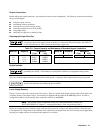
Module Slot Locations/Addresses
Mainframe Mode Switch = MAIN Mainframe Mode Switch = AUX
Slot Location 0 1 23456701234567
Secondary Address 00 01 02 03 04 05 06 07 08 09 10 11 12 13 14 15
For details concerning GPIB cabling and addressing, see "Chapter 2 - Installation" in the Agilent 66000A Mainframe Users
Guide.