


Installation 25
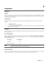
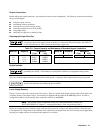
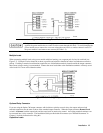
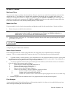
Figure 2-6. Connecting Power Modules in Series
Each power module has a reverse voltage protection diode across its output. If a reverse voltage is
applied, the power module has no control over the current through this diode. To avoid damaging the
power module, never connect it to a reverse voltage that can force it to conduct current in excess of
the power module’s maximum reverse current (see Table 1-2).
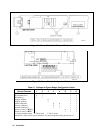
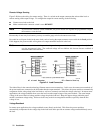
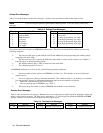
Multiple Loads
When connecting multiple loads to the power module with local sensing, use a separate pair of wires for each load (see
Figure 2-7). Each pair of wires should be as short as possible and twisted or bundled to reduce lead inductance and noise
pickup. If cabling or terminal considerations require the use of distribution terminals located outside the output connector,
then remote voltage sensing is recommended. Connect the sense leads either at the distribution terminals or directly at one
of the loads if it is more critical than the others.
Figure 2-7. Connecting Multiple Loads
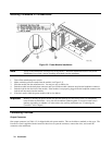
Optional Relay Connector
If you are using the Option 760 output connector with isolation or polarity reversal relays, the output and sense lead
terminal connections are the same as those of the standard output connector. When the output connector Remote/Local
switch is in Remote, both the output leads and the sense leads are under relay control. An existing standard connector can
be converted into a relay connector. The Installation Guide provided with the connector (see "Related Documents" in
Chapter 1) includes instructions for doing this.
Capacitive Loads