


Turn-On Checkout 27
3
Turn-On Checkout
Introduction
This chapter provides a quick test of the power module functions. See "Chapter 4 - Basic Power Module Commands" for
more details of power module operation.
Note These procedures assume you have checked and, if required, correctly set the following switches for each
module:
•
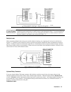
the line voltage switch (see Figure 2-1)
•
the configuration switch (see Table 2-2)
•
the output connector Local/Remote switch
The procedures for doing this are given in Chapter 2.
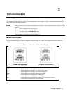
Module Panel Display
The power module display provides the information shown in Table 3-1. There are no operating controls on the power
module.
Table 3-1. Power Module Front Panel Display
INDICATOR FUNCTION
VOLTS
Digital readout of output voltage
AMPS
Digital readout of output current
CV
Lights when power module is in constant voltage mode
CC
Lights when power module is in constant current mode
Addr
Lights when power module is addressed over GPIB
Unr
Lights when power module output is unregulated
Dis
Lights when power module output is disabled
Prot
Lights when power module protection circuit is activated (overvoltage,
overcurrent, overtemperature, or remote inhibit)