


34 Basic Power Module Commands
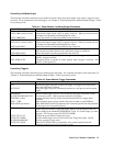
Using the RI/DFI Functions
RI (Remote Inhibit) Input
The signal applied to the mainframe digital connector INH input (see "Chapter 3 Connections" of the mainframe
Installation Guide) is the RI (remote inhibit). The module function switch described in "Chapter 2 - Installation" allows
you to enable or disable the RI input and, when enabled, to specify RI as either latching or nonlatching. If the module
function switch is set to enable RI, then the input signal will disable the power module output. If the function switch is also
set to RI nonlatching, then removing the signal from the INH input restores the power module output. If the function switch
is set to RI latching, an RI status bit is latched and the power module remains disabled after the input signal is removed.
The RI status bit is removed either by reading the Status Questionable Event register (STAT: QUES?) or by clearing it
(*CLS). See the Programming Guide for specifics.
The detected RI bit can be used to generate a DFI signal that appears at the mainframe FLT output. This signal, in turn, can
be wired to the RI inputs of other power modules to also disable their outputs (see the wiring diagram in Chapter 3 of the
mainframe Installation Guide).
DFI (Discrete Fault Indicator) Output
When the DFI function is enabled (OUTP:DFI ON), you can program the Status Subsystem to cause any status condition
(including RI) to generate a DFI output, which appears as a TTL low-true signal at the mainframe digital connector FLT
output. See "Chapter 4 - Status Reporting" in the Programming Guide for details of programming the Status Subsystem.
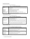
Table 4-6. DFI Output Commands
Command Function
OUTP:DFI ON Enables the DFI function.
OUTP:DFI OFF Disables the DFI function.
OUTP: DFI: SOUR LINK Specifies the source for DFI events. The only source is LINK.
OUTP: DFI: LINK <parameter> Specifies what power module status events are linked to the DFI function. Table 3-1
in the Programming Guide identifies all the DFI link parameters.
Only one parameter may be specified for OUTP: DFI: LINK, such as OUTP: DFI: LINK CC. However, you can specify
entire status groups by specifying a summary bit. For example, OUTP: DFI: LINK QUES specifies the Questionable Status
summary bit, which is the logical OR of OV, OC, OT, RI, and UNR. The default link parameter SUM3 is the logical OR of
the QUES, OPER, and ESB summary bits. This gives DFI access to all three status register groups (see "Chapter 4 - Status
Reporting" in the Programming Guide for more information).
Changing The Power On State
Switch 6 of the module function switches (see "Chapter 2 - Installation") determines the state of the power module when
you turn it on. With the switch in the factory-default position (1), the module turns on in the reset (*RST) state. You will
find the parameters for this state listed under the *RST command in "Chapter 3 - Language Dictionary" of the
Programming Guide. If you store your own parameters in location 0 (*SAV 0), and set the switch to 0, then the module
will assume that state when you turn it on.
Note The *RST state is a safe turn-on state that should not be replaced without careful consideration.