


18 Installation
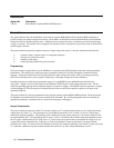
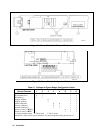
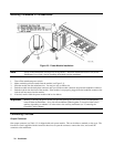
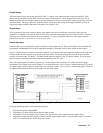
Figure 2-1. Power Module Line Fuse and Switches
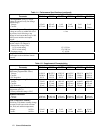
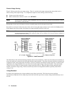
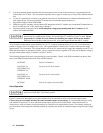
Figure 2-2. Power Module Configuration Switch
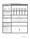
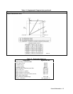
Table 2-1. Settings for Power Module Configuration Switch
Required Switch Setting
Desired Function 1 2 3 4 5 6 7* 8*
RI disabled 0 0 1 1
RI unlatched (live) 0 1 1 1
RI latching † 1 1 1 1
Display disabled 0 1 1
Display enabled † I 1 1
Inhibit calibration 0 0 1 1
Factory calibration 0 1 1 1
Normal calibration † 1 1 1 1
Power on state is *RCL 0
011
Power on state is *RST†
111
†= factory default setting "0" Off or open "1" On or closed.
*Positions 7 and 8 are for service functions. For normal operation, they must be set to 1.