


Installation 21
Output Connections
Before making the actual connections, you must decide on the system configuration. The following factors are described in
the rest of this chapter:
■ using the correct wire size
■ maintaining isolation guidelines
■ selecting local or remote voltage sensing
■ connecting modules in series or in parallel
■ using output relays
■ connecting to capacitive or inductive loads
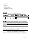
Selecting the Proper Wire Size
Fire Hazard. To satisfy safety requirements, load wires must be large enough not to overheat when
carrying the short-circuit output current of the device connected to the power module. See Table 2-2
for the characteristics of AWG (American Wire Gage) copper wire.
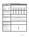
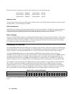
Table 2-2. Current Capacity and Resistance of Stranded Copper Conductors
AWG No. *Ampacity **Resistance AWG No. *Ampacity **Resistance
(Ω/m Ω/ft)
(Ω/m Ω/ft)
20 8.33 0.0345 0.01054 12 40 0.0054 0.00165
18 15.4 0.0217 0.00663
*In free air **At 20
°
C
16 19.4 0.0137 0.00417
14 31.2 0.0086 0.00262
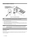
Output Isolation
The output connector ground terminal is a low-noise ground provided for convenience, such as for
grounding wire shields. This terminal is not designed to function as an equipment safety ground.
The power module output terminals are isolated from earth ground. If required, either output terminal may be grounded.
The potential between either output terminal and ground must not exceed ±240 Vdc. Failure to
observe this restriction may damage the power module.
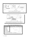
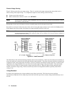
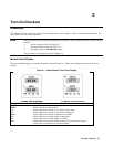
Local Voltage Sensing
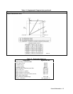
Figure 2-4A shows the load connection for local sensing. There is a switch on the output connector that selects either local
or remote sensing of the output voltage. The connector is shipped with the switch in the LOCAL position. In order to
configure the output for local sensing, make certain this switch is set to LOCAL.
Note The position of the Local/Remote switch also can be determined by software (see
VOLT:SENS:SOUR? in "Chapter 3 - Language Dictionary" of the Programming Guide).
With local sensing, the power module voltage readback circuit senses the voltage at the output terminals. Since this does
not compensate for voltage drops in the terminal screw connections and output leads, use Local sensing only in applications
requiring low output currents or where the load regulation is not critical.