


36 Calibration
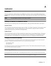
Equipment Required
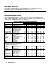
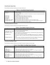
The equipment listed in Table A-1, or equivalent, is required for calibration.
Table A-1. Equipment Required for Calibration
Equipment Characteristics Recommended Model
Voltmeter
D-c accuracy 0.005%, 6 digits; resolution 1
µ
V
Agilent 3458A
Shunt
Agilent 66101A,
66102A
0.01
Ω
, 100 A, 100 W, 0.04% @ 100 W, 0.01% @ 1W,
power coeff. 0.0004%/watt in air
Guildline 9230/100
Agilent 66103A,
66104A, 66105A,
66106A
0.1
Ω
, 15 A, 25 W, 0.04% @ 25 W, 0.01% @ 1W, power
coeff. 0.002%/watt in air
Guildline 9230/15
GPIB Controller or
Keyboard
HP Vectra (or IBM compatible) with GPIB Interface or Agilent BASIC series Agilent 66001A
MPS
Calibrating Voltage
Calibration may cause dangerous voltages to be present at the power module output.
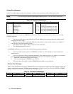
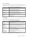
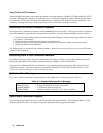
The following procedure calibrates the output voltage and the overvoltage protection (OVP). During voltage calibration,
you will enter two readings from the external DVM. You must calibrate the voltage before calibrating the OVP. You do
not have to enter any external readings when calibrating the OVP.
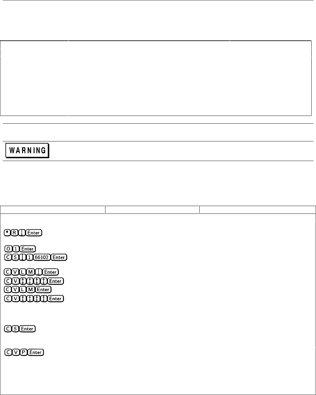
Table A-2. Voltage Calibration Procedure
Keyboard Entry Controller Entry † Function
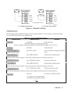
Connect the equipment as shown in Figure A-lA
Output Voltage Calibration
*RST Reset the power module
(Before proceeding, set the module output, via the keyboard or the GPIB, for 1.0 V at 0.5 A)
OUTP ON Enable the output
CAL:STAT 1,66102
Using your password, enable the calibration
mode
CAL:VOLT:LEV MIN Select the lower calibration point
CAL: VOLT: DATA <NRf> Enter the digital voltmeter reading
CAL:VOLT:LEV MAX Select the upper calibration point
CAL:VOLT:DATA <NRf> Enter the digital voltmeter reading
Note: The following step overwrites the existing voltage calibration constants stored in nonvolatile memory.
CAL:SAV Save the new calibration constants
Overvoltage Protection Calibration
If the optional output relay is installed, either disconnect it or set it to the OFF (open) state.
CAL:VOLT:PROT Perform OVP calibration
Note: It takes a few seconds for the power module to make the measurement. When completed, the new constant is
automatically stored in nonvolatile memory.
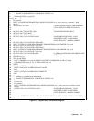
† See Figure A-2 for program listing.
‡ Enter the voltage measured by the external digital multimeter.