


Basic Power Module Commands 33
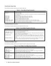
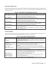
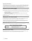
Controlling List-Mode Output
The following commands control the power module list-mode voltage and current output. Lists require a trigger to begin
execution. For an explanation of lists and triggers, see "Chapter 5 - Synchronizing Power Module Output Changes": in the
Programming Guide.
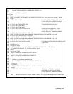
Table 4-4. Power Module List-Mode Output Commands
Command Function
CURR:MODE LIST Sets the current mode to list (as opposed to fixed).
LIST:CURR <value>,<value> Programs the output current values (or points) in the list. When you execute the list,
the output will sequentially step through the list values.
LIST:CURR:POIN? Returns the number of points programmed in the current list.
VOLT:MODE LIST Sets the voltage mode to list (as opposed to fixed).
LIST:VOLT <value>,<value> Programs the output voltage values (or points) in the list. When you execute the list,
the output will sequentially step through the list values.
LIST:VOLT:POIN? Returns the number of points programmed in the voltage list.
LIST:DWEL <value>,<value> Programs the dwell value, in seconds, for each value in a voltage or current list.
There must be one dwell value for each value in the voltage or current list.
LIST:DWEL:POIN? Returns the number of points programmed in the dwell list.
LIST: STEP ONCE Commands the list to execute only one value (point) when a trigger is received. This
specifies a trigger-paced list.
LIST: STEP AUTO Commands the list to execute all values (points) when a trigger is received. This
specifies a dwell-paced list.
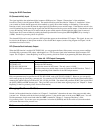
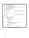
Controlling Triggers
The following commands control the power module trigger subsystem. For a detailed description of this subsystem, see
"Chapter 5 - Synchronizing Power Module Output Changes": in the Programming Guide.
Table 4-5. Power Module Trigger Commands
Command Function
INIT Initiates the trigger subsystem to detect one trigger. No triggers will be processed
unless the subsystem is initiated.
INIT:CONT
Keeps the trigger subsystem continuously initiated so it will process each incoming
trigger.
TRIG:SOUR
BUS|EXT|HOLD|LINK| TTLT
Specifies which trigger source is to be accepted by the trigger subsystem (see the
Programming Guide). HOLD prevents response to all triggers.
TRIG:DEL <value> Programs the delay time (in seconds) between the detection of a trigger and its
execution.
TRIG *TRG Either command sends a trigger signal to the power module over the GPIB bus.
TRIG:LINK <parameter> When TRIG:SOUR LINK is programmed, this command specifies the link parameter
for the trigger (see Programming Guide).
OUTP: TILT ON
Enables the power module Trigger Out signal, which is a 20-µs negative-true TTL
pulse available at the mainframe TRIGGER OUT jack. To use this output, you must
program a TTLT trigger source (OUTP:TTLT:SOUR).
OUTP: TTLT OFF Disables the power module Trigger Out signal.
OUTP:TTLT:SOUR
BUS|EXT|HOLD|LINK
Specifies which trigger source is to be used for the Trigger Out signal. HOLD
prevents a response to any source.
OUTP:TTLT:LINK When OUTP: SOUR LINK is programmed, this command specifies the link
parameter for the trigger (see Programming Guide).