


3 Making Measurements
28 N9340A User’s Guide
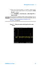
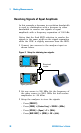
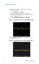
Resolving Signals of Equal Amplitude
In this example a decrease in resolution bandwidth
is used in combination with a decrease in video
bandwidth to resolve two signals of equal
amplitude with a frequency separation of 100 kHz.
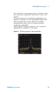
Notice that the final RBW selection to resolve the
signals is the same width as the signal separation
while the VBW is slightly narrower than the RBW.
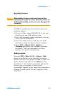
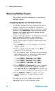
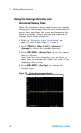
1 Connect two sources to the analyzer input as
shown below.
Figure 3
Frequency
Enter
7
MOD
On/ O f f
RF
4
1
0
2
9
6
3
On/ O f f
Amplitude FM
Utility
LF Out
Preset
Local
AM I/Q
File
TriggerPulseM
·
Sweep
8
5
Remote
Standby
On
N9310A
RF Signal Generator 9 kHz - 3.0 GHz
REVERSE PWR
4W MAX 30VDC
LF OUT RF OUT 50
FUNCTI ON S
Freque ncy
Enter
7
MOD
On/ Off
RF
4
1
0
2
9
6
3
On/ Off
Ampli tude FM
Utility
LF Out
Preset
Local
AM I /Q
File
Trigger
PulseM
·
Sweep
8
5
Remote
Standby
On
N9310A
RF Signal Generator 9 kHz - 3.0 GHz
REVERSE PWR
4W MAX 30VDC
LF OU T RF OUT 5 0
FUNCTIONS
Directional
coupler
Signal generator
Signal generator
Setup for obtaining two signals
2 Set one source to 300 MHz. Set the frequency of
the other source to 300.1 MHz. Set both source
amplitudes to –20 dBm.
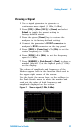
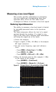
3 Setup the analyzer to view the signals:
• Press [PRESET].
• Press [FREQ] > {Center Freq} > 300.05 > {MHz}.
• Press [SPAN] > {Span} > 2 > {MHz}.
• Press [BW/SWP] > {RBW} > 30 > {kHz}.