


3 Making Measurements
40 N9340A User’s Guide
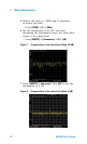
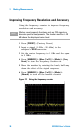
Third-Order Intermodulation Distortion
Two-tone, third- order intermodulation distortion is
a common test in communication systems. When
two signals are present in a non-linear system,
they may interact and create third-order
intermodulation distortion (TOI) products that are
located close to the original signals. System
components such as amplifiers and mixers
generates these distortion products.
In this example we test a device for third-order
intermodulation using markers. Two sources are
used, one set to 300 MHz and the other to
301 MHz.
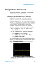
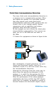
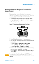
1 Connect the equipment as shown in figure below.
This combination of signal generators, low pass
filters, and directional coupler (used as a
combiner) results in a two- tone source with very
low intermodulation distortion.
Although the distortion from this setup may be
better than the specified performance of the
analyzer, it is useful for determining the TOI
performance of the source/analyzer combination.
After the performance of the source/analyzer
combination has been verified, the DUT (Device
under test, for example, an amplifier) would be
inserted between the directional coupler output
Frequency
Enter
7
MOD
On/Off
RF
4
1
0
2
9
6
3
On/Off
Amplitude FM
Utility
LF Out
Preset
Local
AM I/Q
File
TriggerPulseM
·
Sweep
8
5
Remote
Standby
On
N9310A
RF Signal Generator 9 kHz - 3.0 GHz
REVERSE PWR
4W MAX 30VDC
LF OUT RF OU T 5 0
FUNCTIONS
Frequency
Enter
7
MOD
On/ Off
RF
4
1
0
2
9
6
3
On/ Off
Amplitud e FM
Utility
LF Out
Preset
Local
AM I/Q
File
TriggerPulseM
·
Sweep
8
5
Remot e
Standby
On
N9310A
RF Signal Generator 9 kHz - 3.0 GHz
REVERSE PWR
4W MAX 30VDC
LF OUT RF OUT 50
FUNCTIONS
Signal generator
Signal generator
Directional
coupler