


Making Measurements 3
N9340A User’s Guide 39
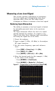
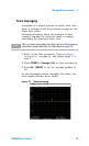
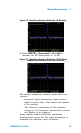
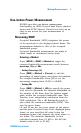
Figure 14 Identifying Analyzer Distortion (O dB atten)
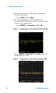
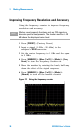
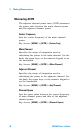
8 Press [AMPTD] > {Attenuation} > 10 > {dB} to
increase the RF attenuation to 10 dB.
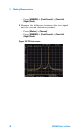
Figure 15 Identifying Analyzer Distortion (10 dB atten)
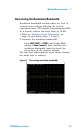
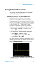
The marker amplitude readout comes from two
sources:
• Increased input attenuation causes poorer
signal-to-noise ratio. This causes the marker
to be positive.
• The reduced contribution of the analyzer
circuits to the harmonic measurement causes
the Marker to be negative.
Large marker readout indicates significant
measurement errors. Set the input attenuator to
minimize the absolute value of marker.