


3 Making Measurements
52 N9340A User’s Guide
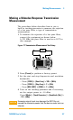
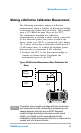
2 Connect the tracking generator output of the
analyzer to the directional bridge or coupler.
3 Connect the analyzer input to the coupled port
of the directional bridge or coupler.
4 Press [Preset] to perform a factory preset.
5 Turn on the tracking generator and if necessary,
set the output power to –10 dBm:
Press [Mode] > {Track Generator} > {Amplitude (On)} >
–10 > {dBm}
6 Set the start and stop frequencies and resolution
bandwidth:
• Press [FREQ] > {Start Freq} > 100 > {MHz}
• Press [FREQ] > {Stop Freq} > 1 > {GHz}
• Press [BW/Avg] > {RBW} > 1 > MHz
7 Replace the DUT with a short circuit.
8 Normalize the trace:
Press [MEAS] > {Normalize} > {Store Ref (1 → 4)}>
{Normalize (On)}
This activates the trace 1 minus trace 4 function
and display the results in trace 1.
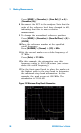
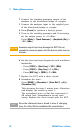
The normalized trace or flat line represents 0
dB return loss. Normalization occurs each
sweep. Replace the short circuit with the DUT.
CAU-CAUTION
Excessive signal input may damage the DUT. Do not
exceed the maximum power that the device under test can
tolerate.
NOTE
Since the reference trace is stored in trace 4, changing
trace 4 to Clear Write invalidates the normalization.