


Making Measurements 3
N9340A User’s Guide 51
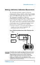
Making a Reflection Calibration Measurement
The following procedure makes a reflection
measurement using a coupler or directional bridge
to measure the return loss of a filter. This example
uses a 370 MHz low-pass filter as the DUT.
The calibration standard for reflection
measurements is usually a short circuit connected
at the reference plane (the point at which the
device under test (DUT) is connected.) See Figure
19. A short circuit has a reflection coefficient of 1
(0 dB return loss). It reflects all incident power
and provides a convenient 0 dB reference.
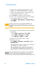
1 Connect the DUT to the directional bridge or
coupler as shown below. Terminate the
unconnected port of the DUT.
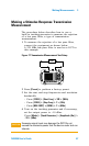
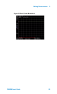
Figure 20 Reflection Measurement Short Calibration Test
Setup
N9340A
HANDHELD SPECTRUM ANALYZER
100
kHz - 3 .0
GHz
PRESET
ENTER
FREQ SPANAMPT D
BW/
SWP
SYS MODE MEAS TRACE
ESC/CLR
2
DEF
3
GHI
1
ABC
5
MNO
4
JKL
6
PQR
8
VWX
7
STU
9
YZ_
0
SAVE
LIMIT
MARKER
Coupled
Port
Short
Circuit
DUT
Or
NOTE
If possible, use a coupler or bridge with the correct test
port connector for both calibrating and measuring. Any
adapter between the test port and DUT degrades
coupler/bridge directivity and system source match.
Ideally, you should use the same adapter for the
calibration and the measurement. Be sure to terminate the
second port of a two port device.