


Making Measurements 3
N9340A User’s Guide 47
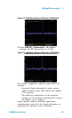
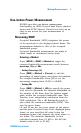
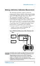
Making a Stimulus Response Transmission
Measurement
The procedure below describes how to use a
built-in tracking generator to measure the rejection
of a low pass filter, a type of transmission
measurement.
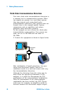
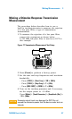
1 To measure the rejection of a low pass filter,
connect the equipment as shown below.
A 370 MHz low-pass filter is used as a DUT in
this example.
Figure 17 Transmission Measurement Test Setup
N9340A
HANDHELD SPECTRUM ANALYZER
100
kHz - 3.0
GHz
PRESET
ENTER
FREQ SPANAMPTD
BW/
SWP
SYS MODE MEAS TRACE
ESC/CLR
2
DEF
3
GHI
1
ABC
5
MNO
4
JKL
6
PQR
8
VWX
7
STU
9
YZ_
0
SAVE
LIMIT
MARKER
DUT
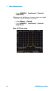
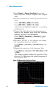
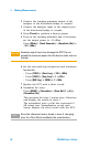
2 Press [Preset] to perform a factory preset.
3 Set the start and stop frequencies and resolution
bandwidth:
• Press [FREQ] > {Start Freq} > 100 > {MHz}
• Press [FREQ] > {Stop Freq} > 1 > {GHz}
• Press [BW/SWP] > {RBW} > 1 > {MHz}
4 Turn on the tracking generator and if necessary,
set the output power to –10 dBm:
Press [Mode] > {Track Generator} > {Amplitude (On)} >
–10 > {dBm}.
CAU-CAUTION
Excessive signal input may damage the DUT. Do not
exceed the maximum power that the device under test can
tolerate.