


14 AR700 Series Router
C613-03087-00 Rev E
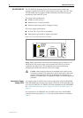
Redundant Power
Supply (RPS)
AC models of the AT-AR745 can be used in conjunction with the AR740 RPS.
Each AR740 RPS can provide power supply and mains circuit redundancy for
up to two AT-AR745s or AT-AR725s. For more information on the AR740 RPS,
see “AR740 RPS Redundant Power Supply (AT-AR725, AT-AR745 only)” on
page 43.
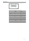
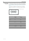
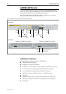
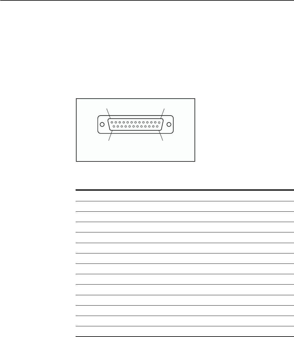
For connection to an AR740 RPS, the AT-AR745 router has a female DB25
connector on its rear panel (Figure 6). Pin outs for the connector are listed in
Table 3.
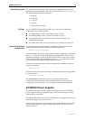
Figure 6: DB25 female connector pinout for an RPS on the AT-AR745 rear panel
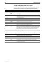
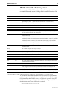
Table 3: DB25 RPS power connector pin out on the AT-AR745
Pin Function Direction
1, 25 Keying -
2, 14 +12 V input
3-5, 15-17 +5 V input
6-8, 18-20 0 V input
9 -12 V input
10 VCC output
11 Main PSU error output
12 Main fan error output
13 RPS disconnected input
21 Sense 0 V output
22 Sense +5 V output
23 RPS PSU error output
24 RPS fan error input
Pin 25
Pin 14
Pin 13
Pin 1
A740db25