


52 AR700 Series Router
C613-03087-00 Rev E
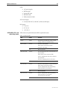
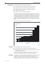
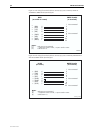
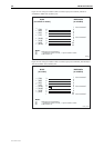
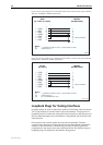
Figure 21: Pin wiring for terminal cable to connect asyn port on AR725, AR745 or
AT-AR024 to DB25 female (terminal) port
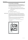
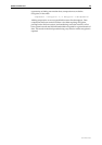
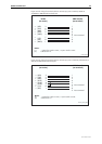
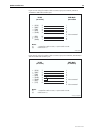
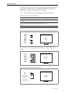
Figure 22: Pin wiring for terminal cable to connect asyn port on AR750S, AR750S-DP or
AR770S to DB25 female (terminal) port
RJ45
(to switch or router)
DB25 Female
(to terminal)
1
2
3
4
5
6
7
8
20
22
5
6
7
8
4
3
2
1
←
→
←
→
→
←
←
←
(RXD)
(TXD)
(CTS)
(RTS)
(GND)
(DTR)
(DCD)
(RING)
Not connected
Not connected
Notes:
(1) Other pins are not connected.
(2) → Output from switch or router; ← Input to switch or router.
(3) Cable version 1.0.
TERMINAL
RJ-45
(to router)
DB25 Female
(to terminal)
1
2
3
4
5
6
7
8
20
22
6
3
8
1
4
5
2
7
←
→
←
→
→
→
→
←
(RXD)
(TXD)
(CTS)
(RTS)
(GND)
(GND)
(DTR)
(DCD)
Not connected
Not connected
Not connected
Notes:
(1) Other pins are not connected.
(2) → Output from switch or router; ← Input to switch or router.
(3) Cable version 1.0.
terminal_ar750