


Hardware Reference 23
C613-03087-00 Rev E
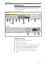
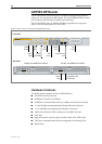
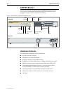
AR750S-DP LEDs and what they mean
Functions of the AR750S-DP LEDs are shown in the following table. Additional
LEDs may be present if a PIC is installed. Functions of PIC LEDs are described
in the Port Interface Card Hardware Reference.
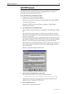
LED State Function
Status PSU 1..2 Green The router is ON, and is receiving power from the PSU
indicated by the LED.
Amber There is a fan or power fault.
Status/SYS Off Normal operation.
Amber Lit briefly during router startup, or if the router is
malfunctioning.
Flashing
3 Flashes
6 Flashes
7 Flashes
There is a fault. To check the router’s fan speed,
temperature, and internal voltages, use the show
system command.
There is an internal power supply fault in the router.
The router temperature is too high or too low.
The router has both an AC and a DC power supply
connected to it. The router only supports dual power
supplies when the PSUs have the same current type.
ETH0 / ETH1
L/A
Green The Eth port has a 100 Mbps link.
Amber The Eth port has a 10 Mbps link.
Flashing Data is being transmitted or received on the Eth port.
ETH0 / ETH1
D/C
Green The Eth port is operating at full duplex.
Amber The Eth port is operating at half duplex.
Amber flashing There is a collision on the Eth port.
PORT 1..5
L/A
Green The switch port has a 100 Mbps link.
Amber The switch port has a 10 Mbps link.
Flashing Data is being transmitted or received on the switch
port.
PORT 1..5
D/C
Green The switch port is operating at full duplex.
Amber The switch port is operating at half duplex.
Amber flashing There is a collision on the switch port.
PIC0
PIC1
Green A port interface card (PIC) is correctly installed and has
been detected by the router.