


6 AR700 Series Router
C613-03087-00 Rev E
AR725 Router
The AT-AR725 router consists of a base CPU card, enclosure and power supply.
The base CPU card supports dual 10/100 autonegotiating Ethernet LAN (eth)
ports and two asynchronous RS-232 ports.
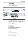
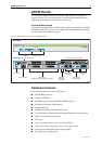
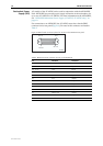
Figure 1: Front and rear panels of the AR725 Series router
Figure 1 shows the AT-AR725 router’s front and rear panels (with a PIC
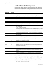
installed in each PIC bay). “AR725 LEDs and what they mean” on page 10 lists
functions of the AT-AR725’s LEDs. Additional rear panel LEDs may be present
if PICs are installed. Functions of LEDs on PICs are described in the Port
Interface Card Quick Install Guide and Port Interface Card Hardware Reference.
Hardware Features
Main hardware features of the AT-AR725 are:
■ 80 MHz RISC processor
■ 1 MByte of EPROM
■ 128 MBytes of synchronous DRAM (DIMM module)
■ 16 MBytes of on-board flash memory
■ CompactFlash slot
■ 128 KBytes of battery backed SRAM
■ 2 high performance autonegotiating full duplex 10/100 Fast Ethernet LAN
ports
■ 2 RS-232 asynchronous serial ports
■ 2 PIC bays
■ A PAC compression/encryption card slot
■ Connector for a Redundant Power Supply (RPS)
■ -48 V DC power supply option
Asynchronous
ports
Power switch
AC power inlet
Mac engine LEDs
and base LEDs
Ethernet ports
and LEDs
Base LEDs
Two PIC bays with PICs installed
DC power inlet for RPS
Rear Panel
Front Panel
Compact Flash
725FRP
Data
ETH
Link
Data
ETH
Link
AC POWER
100-240 VAC
50-60 Hz
1.0 A
5V/5.5A
12V/1.0A
-12V/0.1A
RPS DC POWER
L/A L/A
100M
ETHERNET 1
ENGINE
ACT
PWR
DAT
RUN
ER
SYS
CLR
SEC
PORT 1 PORT 0
PIC 0
BASE
PIC 1
PIC 0
100M
PIC 1
ETHERNET 0
DISCONNECT POWER BEFORE INSTALLING/REMOVING PIC
STATUS
SECURITYPOWER RUN SYSTEM CLEAR
AR725
Enterprise Router
ACTIVITY
COMPACT FLASH