


Hardware Reference 57
C613-03087-00 Rev E
Some interfaces (e.g., the synchronous ports) require a specially built external
testing device (available from your authorised Allied Telesis distributor or
reseller) to be used in conjunction with the Test Facility.
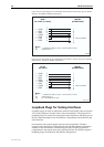
Table 12 lists the loopback plug wiring diagrams for each interface type.
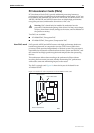
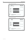
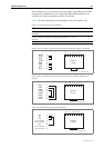
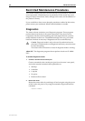
Figure 31: RJ-45 loopback plug for testing asyn interfaces AR725, AR745 or AT-AR024
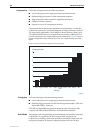
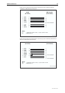
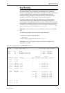
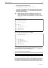
Figure 32: RJ-45 loopback plug for testing asyn interfaces on AR750S, AR750S-DP, or
AR770S
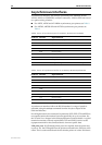
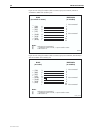
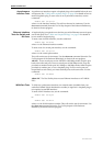
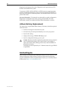
Figure 33: Ethernet twisted pair (TP) loopback plug
Table 12: Loopback plug pin wiring diagrams
Physical Interface Loopback Pin Wiring Diagram
RJ-45 asynchronous interface on AR725, AR745 or
AT-AR024
Figure 31
RJ-45 asynchronous interface on AR750S, AR750S-DP or
AR770S
Figure 32
Ethernet TP interface Figure 33
1
2
3
4
5
6
7
8
(RING)
(DCD)
(DTR)
(GND)
(RXD)
(TXD)
(CTS)
(RTS)
12345678
End view
of plug
RJ45LOOP_ar7x5
1
2
3
4
5
6
7
8
(RTS)
(DTR)
(TXD)
(GND)
(GND)
(RXD)
(DCD)
(CTS)
12345678
End view
of plug
rj45loop_ar750
Not connected
Not connected
Not connected
Not connected
1
2
3
4
5
6
7
8
12345678
End view
of plug
TX+
TX-
RX+
RX-
TPLOOP_ar700